Carbon Fiber Layup Design Rules for Structural Hardware Parts
Four design rules determine whether carbon fiber parts handle load or fail in the mold.
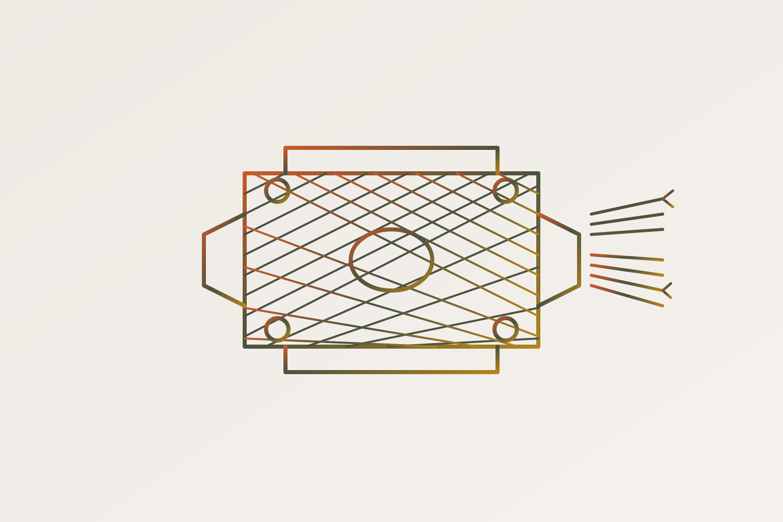
Carbon fiber fails or succeeds based on decisions made before anyone cuts a single ply. Orientation, stacking order, symmetry, balance: these choices determine whether a part carries load the way it's supposed to, or twists, warps, and delaminates under conditions the metal equivalent would shrug off. Carbon fiber demands its own design logic, separate from metal substitution habits. Its strength runs in one direction along the fiber, and if that direction isn't planned into the laminate on purpose, the part won't perform no matter how good the geometry looks in CAD.
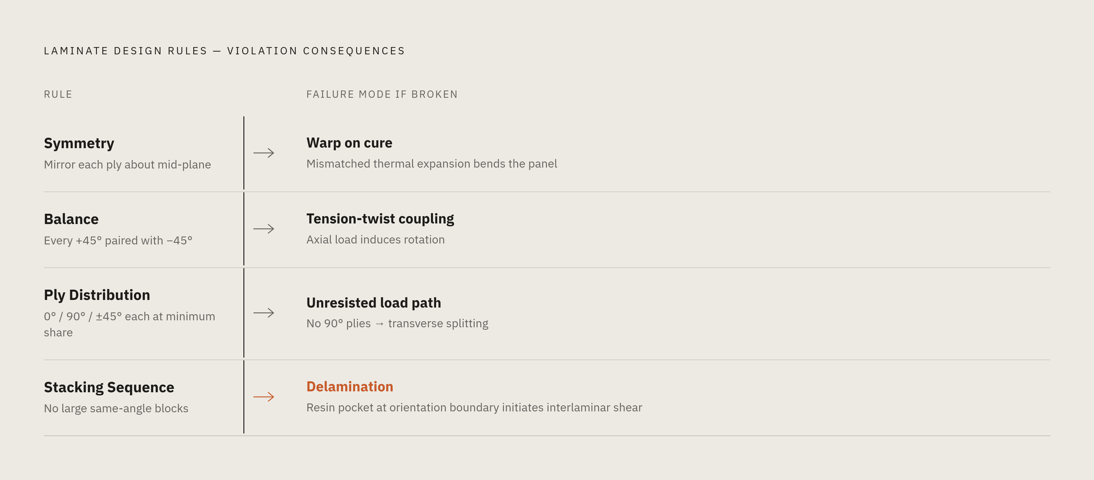
Structural carbon fiber laminates are governed by four interlocking rules, each with a distinct failure mode when broken. Symmetry requires every ply above the mid-plane to be mirrored below it; violate it and the laminate warps during cure from mismatched thermal expansion before any mechanical load is ever applied. Balance requires every +45° ply to be paired with a −45° ply somewhere in the stack; skip the counterpart and in-plane tension couples into twist, so a part loaded in straight pull wants to rotate. Ply orientation distribution sets the share of 0°, 90°, and ±45° content to match the load path, with no orientation family allowed to drop to zero, because a stack with no 90° plies has nothing resisting transverse splitting along the fibers. Stacking sequence controls where each orientation sits within that balanced, symmetric stack: concentrating too many plies of one angle together creates a resin-rich pocket at the orientation boundary, which is exactly where interlaminar shear initiates delamination, while ply drops stacked at one location instead of staggered along the part act as a notch cut into the structure.
Most CFRP failures actually start in the design desk, weeks before anyone touches the layup room. Wrong ply orientation. Asymmetric stacking. A joint that pulls straight through the laminate instead of along it. The mechanical behavior of a composite part depends on fiber angle and stack order down to the degree; get the global orientation wrong and performance drops off fast, not gradually. There's no bulk isotropy to fall back on. Aluminum forgives you a little because it behaves the same in every direction. Carbon fiber's strength lives locally, ply by ply, angle by angle, with no such cushion.
Engineers repeatedly treat carbon fiber as a shape problem, modeling the geometry first and figuring out the material and layup afterward. That order gets it backward. It throws away the one thing that makes composites worth the trouble in the first place, which is the ability to tune stiffness and strength in specific directions by controlling exactly where the fiber goes. Manufacturability and structural performance need to enter the conversation at the concept stage, not after the mold's already been cut. What follows is a working set of rules for getting the layup right the first time, organized around what breaks when each rule gets ignored.
Symmetry: the rule that prevents warping without any load applied
Symmetry gets measured against the laminate's mid-plane. Every ply above that line needs a match below it: same orientation, same thickness, same material. Skip this and the part can fail before it ever sees a working load.
Here's why. Carbon fiber has a negative coefficient of thermal expansion along the fiber direction, meaning it shrinks a little as it heats up, which is the opposite of what most materials do. During cure, the laminate goes through a real temperature swing, often substantial in an autoclave cycle. If the top half of the stack and the bottom half aren't mirror images of each other, they respond to that temperature change differently. That mismatch creates an internal bending moment, and the part warps or twists while it's still curing, long before anyone applies a mechanical load to it. Asymmetry also concentrates stress at the interface between the unbalanced sections instead of spreading it through the laminate the way a symmetric stack does.
The practical rule: a layup written as [0/90/45/-45] isn't finished. The full symmetric stack reads [0/90/45/-45/-45/45/90/0], mirrored around the center, not repeated. This same CTE logic extends to tooling. Carbon fiber molds get used for carbon fiber parts because a steel or aluminum mold, with its own CTE, will pull the part out of shape as it cools from cure temperature. Symmetry carries real structural weight for load-bearing hardware, not just cosmetic tidiness. It's the floor everything else gets built on.
Balance: pairing ±45° plies so shear loads don't induce twist
Balance is a different requirement from symmetry, and it's easy to conflate the two. A laminate is balanced when every +45° ply has a matching −45° ply somewhere in the stack. They don't need to sit next to each other. They just both need to exist, in equal numbers.
Skip this and tension turns into rotation. An unbalanced laminate couples in-plane tension with in-plane shear, so a part loaded in straight tension wants to twist, because the fiber angles aren't canceling each other out the way they should. The most common way this happens in practice: a designer adds a +45° ply to pick up shear stiffness, then drops the −45° counterpart to save weight or simplify the stack, not realizing the two were supposed to work as a pair.
Symmetry and balance don't guarantee each other. A laminate can be symmetric about its mid-plane and still be unbalanced in its ±45° ratio, and vice versa; both checks have to happen independently. For anything torsion-dominated, drive shafts, structural tubes, brackets carrying combined loads, balance stops being a refinement and becomes the whole game. An unbalanced tube doesn't just perform poorly under torque. It unwinds.
Ply orientation distribution and what the 60-70 / 30-40 rule actually means
Every structural laminate is built from three orientation families, and each one does a different job. 0° plies carry axial load and set bending stiffness in the primary direction. 90° plies carry transverse load and keep the part from splitting along the fiber line. ±45° plies carry shear and resist diagonal loading in the plane of the laminate.
A common starting point: 60 to 70 percent of the stack in the primary direction, with the remaining 30 to 40 percent split between transverse and shear plies. That's a starting point, not a formula to apply blindly. Shear-dominated or biaxial load cases shift the balance toward more ±45° content. In honeycomb sandwich panels of a given height, for instance, swapping a 0°/90° reinforcement pattern for ±45° has been shown to push shear modulus more than 5 times higher in one plane and more than 4 times higher in the other. Turning the same fiber and resin 45 degrees produces a completely different structural behavior.
Quasi-isotropic layups, typically written [0/±45/90]s, spread stiffness evenly across every direction. They're the right call when load paths are complicated or not well understood. But that even spread comes at a cost: quasi-isotropic stacks give up the peak directional performance that makes carbon fiber worth using over aluminum in the first place. Where the load path is well characterized, a stack loaded heavily toward one direction will beat a quasi-isotropic layup in that direction every time.
One more guardrail worth keeping in mind: don't let any single orientation family drop to a negligible share of total ply count. A stack with zero 90° plies has nothing stopping it from splitting parallel to the fibers under transverse or Poisson-effect loading. And when checking these ratios against a wall thickness target, remember ply thickness runs 0.125 mm to 0.25 mm depending on the prepreg or fabric weight, so the ply count math has to line up with the physical thickness budget, not just the percentage split.
Why does ply stacking order matter, and what fails when it's wrong?
Two laminates can have identical ply counts and identical orientation percentages and still behave completely differently, because stacking order changes interlaminar stress, delamination resistance, bending stiffness distribution, and surface finish independent of everything else.
Outer plies take the abuse first: impact, abrasion, environmental exposure. Putting ±45° or woven plies on the outside improves impact resistance and surface quality. Put 0° plies on the outermost surface instead, and bending stiffness goes up, because those fibers sit farthest from the neutral axis, but impact resistance and interlaminar shear performance both take a hit. Neither choice is universally right. It comes down to what the part actually has to survive in service.
Stack too many plies of the same orientation together and you get a thick, resin-rich pocket at the boundary between orientation blocks, which is exactly where delamination likes to start under interlaminar shear. General practice: avoid grouping a large block of plies of the same angle together without breaking it up with a different orientation. Ply drops, where plies get removed to taper a part's thickness, create their own stress concentration at the drop location. Stagger those drops along the length of the part instead of stacking them all at once, so the load transfers gradually instead of hitting a sudden step.
After the sequence is set, there's a simple check worth running every time: read the stack from the mid-plane outward in both directions. It should read identically both ways. If it doesn't, symmetry's broken somewhere and it's worth finding before the layup goes to cure.
How misalignment and orientation errors degrade structural performance
Carbon fiber's strength runs almost entirely along the fiber axis, and that directionality is unforgiving. Load a ply even a few degrees off its fiber direction and the load starts shedding into the resin matrix, which is dramatically weaker than the fiber itself. The drop in strength isn't gradual. It's steep.
Every major failure theory used in composite design, maximum stress, maximum strain, Tsai-Hill, Tsai-Wu, shows the same pattern: off-axis loading costs you strength fast. A unidirectional laminate loaded exactly along its fiber direction hits peak stiffness and strength. Cross-ply and quasi-isotropic layups trade some of that peak performance away in exchange for more even behavior across directions, and that tradeoff is predictable, but it's not small.
In production, misalignment creeps in from a handful of sources. Hand layup can put a ply down a few degrees off the intended angle without anyone noticing until inspection. Automated fiber placement heads can drift off course steering tows around tight radii. Plies can slip under vacuum bag pressure before cure locks them in place. For any ply doing critical structural work, the drawing needs an angular tolerance called out explicitly, appropriate to the application, and that tolerance needs real verification, not a visual once-over.
There's a second-order effect worth flagging too: orientation error breaks balance. A +45° ply laid down at +47° no longer cancels its −45° counterpart cleanly. That small angular error reintroduces the exact tension-shear coupling the balance rule was supposed to eliminate.
Joint and attachment design for composite structural parts
Carbon fiber's weak axis is through the thickness. Interlaminar tensile strength depends on the resin, not the fiber, so any joint that pulls perpendicular to the ply plane is working against the laminate's worst direction. That's the single most important thing to know before designing a composite joint.
Bonded joints need a wide overlap area to keep adhesive shear stress within allowable limits, and the real danger comes from peel, tension concentrated at the edge of the bond, more than from shear itself. Tapered or stepped scarf joints spread that peel stress out instead of letting it spike at one point. Surface prep matters just as much as the geometry: abrasion, a solvent wipe, and bonding before contamination has a chance to settle back onto the surface.
Mechanically fastened joints work differently. Bolts and rivets create bearing loads around the hole, and CFRP handles bearing reasonably well as long as ±45° plies are present to carry shear around the fastener. Edge distance and end distance rules need careful application, because composite doesn't yield locally to redistribute stress the way metal does. Fastener material selection should account for both CTE compatibility with carbon fiber and galvanic corrosion risk at the interface.
For thin skins or sandwich panels, threaded inserts potted into the core spread pull-out loads across a wider area. A point load applied straight to a thin face sheet crushes the core underneath it and delaminates the skin. And drilling matters more than people expect: carbon fiber needs carbide or diamond tooling with controlled feed rate, because delamination at the hole exit is one of the most common and most preventable failure points in a composite structure, regardless of how well the laminate itself was built. The rule that ties all of this together: keep fastener and bond loads in-plane with the fiber direction of the bearing plies wherever the design allows it. Out-of-plane load at a joint is the fastest route to delamination that exists.
DFM constraints that the laminate rules alone don't capture
Sharp internal corners don't work in composites the way they do in machined metal. Fiber can't wrap a zero-radius corner without bridging, meaning it pulls away from the mold surface and leaves a void or a resin-rich pocket right where the corner is, which becomes a delamination starting point later. General practice: keep the internal radius generous relative to the laminate thickness.
Ply drops need a controlled drop rate, meaning a controlled number of plies removed per unit length, staggered along the part rather than stacked at one location. Stack the drops together and the result behaves like a notch cut into the structure. Automated fiber placement also imposes a minimum ply width; narrower than that and the material can't be placed accurately, and it tends to bridge or wrinkle instead of laying flat.
Undercuts and hard-to-reach layup zones carry real structural consequences, not just added labor. If a technician or an automated head can't physically get a ply flat against the surface, that's a geometry problem that needs solving through split tooling, a design change, or a different placement approach, and any one of those choices can force a change to the structural sequence itself. Tooling CTE matters here too, and it echoes back to the symmetry discussion: a mold that expands or contracts differently than the laminate during cure builds in residual stress that's indistinguishable, later, from stress caused by an actual mechanical load. For autoclave-cured prepreg, that's the reason composite tooling gets paired with composite parts as a default.
All of this needs to surface at the quoting stage, before the ply schedule gets locked in. A geometry change made after the mold already exists is the most expensive redesign loop in composite manufacturing, full stop. And these DFM constraints don't sit separately from the structural rules; they interact. A stacking sequence that looks optimal on paper might call for a ply width or a drop rate the chosen process simply can't execute with any reliability.
Choosing the right process for the part's structural and schedule requirements
Prepreg cured in an autoclave sets the bar. It delivers the highest fiber volume fraction and the tightest control over voids, and it's the proven choice for primary structure. That performance comes with the longest setup time and the highest tooling cost of any composite process, and it's the benchmark every other option gets measured against structurally.
Out-of-autoclave prepreg gets close, with proper process control, and works for plenty of structural parts that don't need aerospace-primary qualification. Tooling investment drops, cycle time shortens, and the part still holds up under real structural load if the process is controlled well.
Wet layup and vacuum infusion sit at the other end: lowest tooling cost, fastest turnaround for a first part, but higher void content and more variability from one part to the next. That variability is the tradeoff, and it needs to be weighed honestly against what the part actually has to do. None of the laminate rules above change based on which process gets picked. Symmetry, balance, orientation, and sequence still have to hold. What changes is how tightly the process can control the execution of those rules, and that's exactly the conversation to have before a mold gets cut, not after.