Draft Angle and Wall Thickness Requirements for Urethane Cast Parts
Minimum draft angles and uniform wall thickness prevent warping and extend mold life.

Urethane casting has a reputation for being forgiving. That reputation is half true, and the false half is exactly where engineers get burned: the draft angle and wall thickness decisions made in CAD, before a mold ever gets cut, decide whether a part releases clean, cures without warping, and holds the tolerance the drawing actually calls for.
For urethane cast parts, general vertical faces need 0.5 to 1 degree of draft as a minimum, ribs need 0.25 to 0.5 degrees per side, and any feature where mold life matters should be designed to 3 to 5 degrees. Wall thickness should stay uniform with a 0.040-inch (1 mm) minimum for most parts, since thickness variations cause differential shrinkage that shows up as warping, sink marks, and dimensional drift. Silicone molds do allow zero-draft vertical walls because the mold peels off rather than ejecting, but every draft-free pull stresses the silicone and accelerates dimensional drift across a production run, so zero draft is technically achievable but not advisable for anything beyond a handful of parts. The practical rule: design to 3 to 5 degrees whenever geometry allows it, and treat zero draft as a last resort, not a routine advantage of the process.
Anyone doing product development runs into this sooner or later: bridge tooling ahead of an injection-molding launch, a low-volume production run, or a prototype batch that needs surface detail no CNC pass can match. The process is simple enough. A master pattern, usually 3D-printed, gets encased in liquid silicone that cures into a mold, and urethane resin gets poured into that mold, cured in an oven, before the flexible silicone gets peeled off the finished part. No hard tooling, no multi-week wait on a mold shop. That's the real appeal.
"Forgiving" is relative, though, and engineers who treat it as absolute are the ones who get burned. Silicone handles undercuts and draft-free walls that would tear a steel mold apart on ejection, and that's exactly the trap: what silicone allows isn't the same as what silicone rewards over dozens of cycles. This piece walks the limits in order: draft angles first, then wall thickness and why uniformity beats any single number, then ribs and bosses as extensions of that same shrink-and-stress logic, and finally the tolerances all of it adds up to.
Does silicone molding really let you get away with zero draft?
In a steel injection mold, draft isn't optional. Skip it, and the part can't eject without tearing up the surface finish, or the mold itself.
Silicone molds peel off parts instead of ejecting them. The mold's own flexibility does the job that draft angle does in hard tooling, which is why zero-draft vertical walls actually work in urethane casting, and undercuts that would demand side-actions in a steel tool often need no special tooling at all in silicone.
Achievable isn't the same as advisable, and this is exactly where engineers overestimate how forgiving the process is. Every pull on a draft-free feature stresses the silicone, and doing that across dozens of cycles wears the mold faster, with dimensional drift creeping in part after part. Draft angle decisions aren't just about getting one part out clean; they're about how many good parts come out of that mold before the dimensions start sliding. Skipping draft to save a design step now just moves that cost onto every cycle after the first.
The tiered draft angle requirements and when each threshold applies
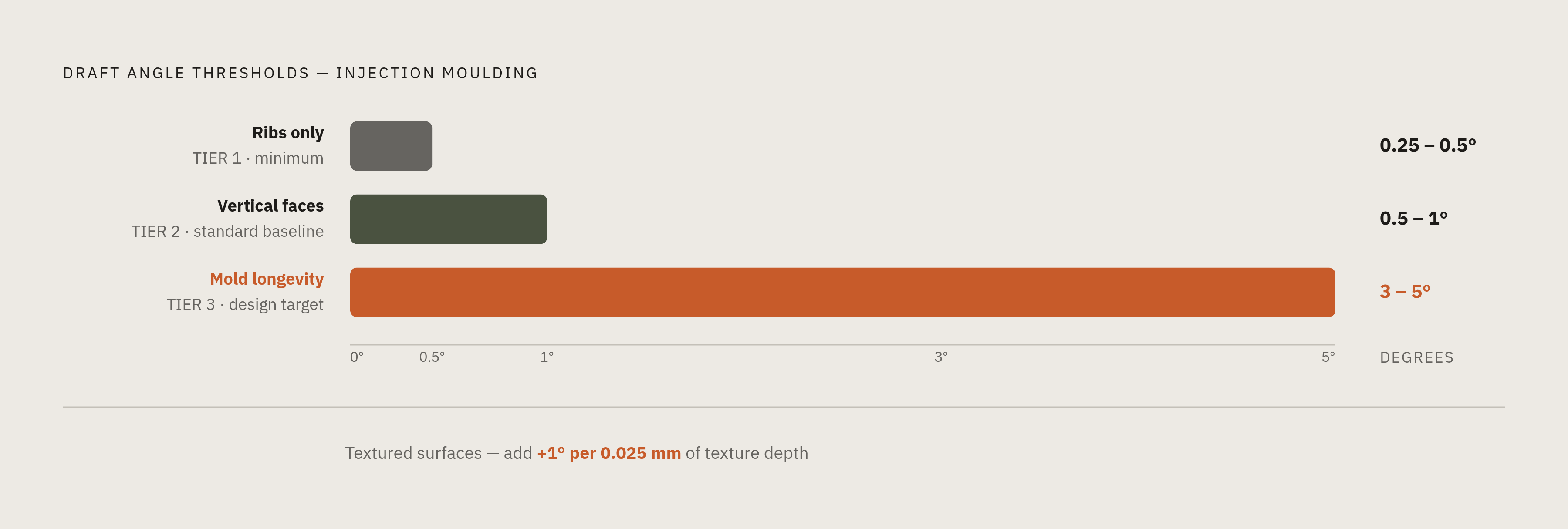
Draft comes in three tiers, and they apply to different situations. Treat them as interchangeable, and a design goes sideways fast.
Ribs need 0.25 to 0.5 degrees of draft per side, applied evenly on both sides. That's the narrowest minimum in the whole process, sitting on a feature that already concentrates material and stress at its base.
General vertical faces need 0.5 to 1 degree as a baseline. This covers most standard geometry, and the 1-degree figure is the safer default once a part gets bigger, since larger surfaces mean more cumulative friction on release.
For mold longevity, 3 to 5 degrees is the number worth designing toward on any feature where draft is geometrically possible. That range cuts extraction stress substantially and stretches how many pulls a single silicone mold gives before it needs replacing.
Textured surfaces carry their own add-on rule: 1.0 degree of extra draft for every 0.025 mm of texture depth. Texture multiplies surface friction, and friction is what the mold fights on every release.
Long, zero-draft features deserve their own flag. The longer a draft-free wall runs, the more cumulative friction builds during extraction, and the risk of breakage climbs with the length of the run, not just the shape of the part.
A short prototype run of a handful of parts can get by on 0.5 to 1 degree, but anyone pulling dozens of parts off the same mold should design to 3 to 5 degrees, full stop. That range pays for itself many times over in mold life and part-to-part consistency. Treating it as optional on a production run is a mistake, not a judgment call.
Why engineers designing bridge-to-injection-molding prototypes should draft from the start
Urethane casting often functions as bridge tooling. The same geometry cast in urethane today might be running in a steel injection mold next year, once volume justifies the cost of hard tooling.
If that urethane prototype got designed draft-free because the silicone allowed it, the CAD file isn't ready for injection molding. Someone has to redesign it, and depending on how far along the project is, that might mean reprinting patterns and re-casting prototypes too. Nobody budgeted for that time.
The move is obvious once you see the tooling path ahead of time: if the part is eventually headed for injection molding, draft it to injection-molding standards now. Silicone accommodates the draft without complaint, and steel tooling demands it later regardless. Skipping this step to save five minutes in CAD is the kind of shortcut that costs a full design cycle down the line.
The same logic covers undercuts. Urethane casting shrugs them off, but bake an undercut into a part headed for injection molding, and it turns into tooling complexity, added cost, and a redesign conversation later. Drafting early costs nothing in urethane casting, while skipping it costs an entire iteration cycle.
Wall thickness minimums and why uniformity matters more than the number itself
Minimum wall thickness scales with part size. Small parts can go down to 0.020 inches (0.5 mm), though that's thin and needs careful geometry around it, while larger parts should hold a 0.040-inch (1 mm) minimum, since bigger parts need more material in the wall to stay structural, both during extraction from the mold and later in use. A practical working range across most applications runs 0.020 to 0.050 inches, leaning thicker as the part gets bigger.
The number matters less than what happens when it's inconsistent, and that's the part most people miss. Urethane resin cures at the same rate everywhere in the mold; it doesn't slow down for thick sections or speed up for thin ones. Thick sections hold heat longer and shrink more as they cool, while thin sections cure faster and pull away from their thicker neighbors while that's happening. That mismatch is where warping, sink marks, internal stress, and dimensional drift all come from, and every one of those defects shows up after the mold's already open: the most expensive point in the whole process to find out something's wrong.
The fix is to taper transitions between thick and thin sections instead of stepping them abruptly. A sudden jump in thickness is exactly the kind of local stress point that turns into a visible defect.
Knife edges, meaning very acute angles where a wall thins out to almost nothing, need blunting with a fillet or chamfer. They're the most extreme version of the thin-to-thick problem, and they concentrate stress in the cured part on top of it.
Thick sections carry a second cost that's easy to overlook: longer oven cure times, and more resin used per part. On a low-volume run, that shows up directly in unit economics.
Rib geometry rules that prevent sink marks and mold stress
Ribs add stiffness without adding bulk, but only when the proportions are right. Get them wrong, and a rib becomes exactly the kind of oversized, thick section that causes the shrink problems described above.
Rib width at the wall intersection should sit at 40 to 60% of nominal wall thickness, keeping local material volume low enough to cure evenly with the wall around it. Rib height shouldn't exceed three times the rib's own width; taller than that, and the rib sinks and pulls hard from the mold. Some guidelines apply a tighter version of the same idea, capping rib thickness at 0.5 times nominal wall thickness. The interior fillet radius at the base of the rib should run at least 25% of the part's wall thickness, which stops stress from concentrating right at the junction and lets resin flow into the rib fully during the pour.
Draft on ribs comes back into play here too, at that same 0.25 to 0.5 degrees per side. A draft-free rib that's also too tall isn't two separate risks; it's one compounded one.
One pattern worth stating flatly: several short ribs spread across a surface beat one long, continuous rib, no exceptions. Multiple shorter ribs deliver comparable stiffness with fewer extraction problems and less concentrated stress, and there's no case where the single long rib wins that trade.
Boss geometry and the sink risk engineers most commonly miss
Bosses, the cylindrical mounting posts that take screws or threaded inserts, are prone to sink marks because their shape naturally piles up material at the base. That's the number-one sink risk engineers overlook, and it catches experienced designers just as often as new ones.
Boss base radius should sit around 25% of nominal wall thickness, limiting how much material accumulates right where it's most vulnerable. Boss height should stay under 60% of nominal wall thickness to keep shrinkage in check. The interior boss fillet radius should be 0.060 inches (1.5 mm), which keeps local thickness down and cuts the odds of a sink mark showing up on the opposite face.
Bosses can be strengthened without thickening the wall by adding gussets at the base, or ribs that tie the boss into a nearby wall. That spreads load and adds stability without creating the bulk that causes sink.
There's a thermal angle here too, and it's the one people forget entirely. An undersized boss base radius piles material up right at the insert zone, and that concentration can actually burn during heat-set installation of a threaded insert. The 25% rule handles this heat failure mode and the sink risk at the same time.
Fillet radii at interior corners and why sharp corners fail in casting
Sharp interior corners are stress risers. Under load, cracks start at the corner and work their way through the wall from there, not the other way around, and sharp corners also block resin from flowing fully into the mold cavity during the pour, which raises the odds of a void forming right at that corner.
The standard fix: interior fillets of at least 0.125 inches on inside corners. That radius does double duty, adding strength to the part and helping resin fill the cavity completely. Ribs and bosses already carry their own fillet rule, tied to 25% of wall thickness; the 0.125-inch figure is the floor for everything else on the part.
What tolerances urethane casting can realistically hold and where the variation comes from
Under tightly controlled conditions, urethane casting typically holds ±0.010 to ±0.015 inches (0.25 to 0.38 mm). Across vendors, the broader cited range runs ±0.010 to ±0.020 inches per inch, depending on part geometry, resin, and mold design. Tighter tolerances, down to ±0.005 inches (0.13 mm), are possible with controlled geometry and careful mold design, but that level belongs on specific critical features, not the whole part.
The per-inch framing matters most for large parts: figure ±0.010 inches for the first inch as a standard tolerance baseline. Dimensional variation accumulates across a big part, which makes urethane casting a poor choice for large parts needing tight positional accuracy across a long span.
Shrinkage drives most of that variation, and it comes from two directions that stack. Urethane resin itself typically shrinks around 0.15%, in a range of 0.10 to 0.20% depending on the specific material and geometry. The silicone mold adds its own behavior on top: condensation-cure silicones shrink roughly 0.5% during cure, while addition-cure silicones behave differently in ways that affect dimensional outcome. Picking condensation-cure silicone when a tight tolerance is on the drawing is how a spec gets blown before the resin ever gets poured. If a critical tolerance is on the print, addition-cure silicone is the safer choice, and the mold chemistry is the half of that equation people forget to check.
Mold degradation adds a third layer that's easy to miss. Silicone molds drift beyond their original dimensional accuracy after enough cycles, and vendors don't always flag that up front. Anyone planning a run that pulls a lot of parts from a single mold needs to account for that drift, not just the resin's shrink rate.
Urethane casting remains more than adequate for most prototyping and low-volume production work, though it doesn't match what CNC machining or hardened production tooling can hold, and pretending otherwise is how a part fails inspection on a feature nobody flagged as critical. Knowing that difference up front decides which features get cast as-is and which ones get machined afterward as a secondary operation.
Applying all of these rules together before the file goes to quote
None of these rules stand alone. Wall thickness sets the boundaries for rib proportions, rib proportions determine how much draft a feature actually needs, and all of it together determines the tolerance the finished part can realistically hold. Get one rule wrong on a design, and two or three more are usually wrong right alongside it.
Before any file goes out for a quote: wall thickness should stay uniform, with a 0.040-inch minimum for most parts and tapered transitions instead of stepped ones. Draft should sit at 0.25 to 0.5 degrees on ribs, 0.5 to 1 degree minimum on vertical faces, and 3 to 5 degrees anywhere mold life matters, with 1.0 extra degree of draft per 0.025 mm of texture depth on textured surfaces. Ribs should run 40 to 60% of wall thickness in width, no taller than three times that width, with a base fillet of at least 25% of wall thickness. Bosses need a base radius around 25% of wall thickness, height capped at 60% of wall thickness, and an interior fillet of 0.060 inches. Interior corners need a fillet radius of at least 0.125 inches. Tolerance expectations should get set going in, using ±0.010 to ±0.015 inches as the working assumption, with tighter tolerances reserved only for the features that actually need them.
For any part on a path to injection molding eventually, draft it to injection-molding standards now. Silicone accommodates that draft today, and steel tooling requires it later regardless. Waiting doesn't save anyone anything.
DFM review at the quoting stage is the cheapest point in the entire process to catch these issues. A knife edge or a draft-free tall boss costs nothing to fix while it's still a CAD file on someone's screen, and catching it after the mold's been cut costs a mold instead.