DFM Checklist for CNC Milled Aluminum Prototypes
Decide alloy and geometry before quoting to control cost and lead time.
A DFM checklist for CNC milled aluminum prototypes isn't a table of tolerance values you paste onto every drawing. It's a sequence of decisions: alloy, geometry, tolerance, finish, and the file package that ties it all together. Get the sequence right and quotes come back faster, cheaper, and closer to what you actually need. Get it wrong and you pay for precision nobody asked for, on features that were never going to fit anyway.
Before sending aluminum CNC milled parts for quoting, confirm the alloy and temper first, 6061-T6 for most work, 7075-T6 only when strength-to-weight is a hard requirement, 2024 only for cyclic fatigue applications, and lock the full designation into the title block. Check geometry next: every inside corner needs a radius of at least one-third the pocket depth, walls should stay at 0.040 inches minimum, pocket depth should not exceed four times the pocket width, and any undercuts or compound angles must be flagged because they change which machine the job runs on. Assign tolerances by zone rather than applying one tight value to the whole drawing: ISO 2768-m covers clearance holes and non-mating surfaces, while tight tolerances belong only on dowel pin slots, bearing bores, and other precision-fit features. The file package should communicate all of this explicitly, alloy and temper in the title block, corner radii and wall thickness called out on the drawing, and tolerances zoned so the shop knows exactly which features require close inspection.
Start with the alloy, because everything downstream depends on it.
Three alloys, three jobs
Nearly every aluminum prototype that goes through a CNC mill lands on one of three alloys: 6061-T6, 7075-T6, or 2024.
6061-T6 is the default. It machines well, resists corrosion, welds fine if you ever need to weld it, and costs less than the alternatives. It's also everywhere, sheet, bar, tube, so lead times stay short and nobody's waiting on a mill run from a specialty supplier. Within the high-strength aluminum alloy market, the 6xxx series holds the largest share, close to 40%, and that share comes almost entirely from enclosures and structural brackets, the exact parts most prototype shops are cutting all day. Unless your design has a specific reason to move off 6061, start there and stay there.
7075-T6 earns its place when strength-to-weight is the actual requirement, not a nice-to-have. Aerospace fittings, high-load brackets, gears, shafts, the parts where shaving grams matters as much as holding up under load. Yet the tradeoffs are real and often glossed over in early design reviews. 7075 costs more per pound, wears out carbide end mills faster because of its zinc content, resists corrosion less well than 6061, and doesn't weld cleanly. On a five-part prototype batch, the tool wear difference barely registers. At production volume, it adds up fast. A lot of engineers spec 7075 out of habit or because it sounds tougher on paper; when that's the case, switching to 6061 usually raises yield and lowers cost.
2024 is the narrow case: fatigue. If the part sees repeated cyclic loading and has to resist crack growth over thousands of cycles, aerospace structural members being the classic example, 2024 is worth the trouble. The 2xxx series work-hardens more aggressively than 6061 or 7075, so the shop needs sharp tooling from the first cut or you'll fight built-up edge and poor surface finish the whole way through. Treating it as a drop-in substitute for 7075 on a whim wastes both money and machine time.
Whichever you pick, lock the temper into the title block. "Aluminum" is not a spec. "6061-T6" is.
What geometry should I check before sending parts for quoting?
Most of the friction in a CNC quote comes down to geometry decisions made before anyone thought about the cutter.
Inside corners need radii, full stop. A rotating end mill can't cut a sharp inside corner; it physically can't get there. Every inside corner needs a radius of at least a third of the pocket depth. Leave it sharp on the drawing, and the shop will add a radius on their own to make the part cuttable, and that radius might not be the one your mating part actually needs. Spec it yourself, and lean generous. Bigger radii also cut down on stress concentration, so there's no real downside to rounding more than the bare minimum.
Wall thickness controls whether the part survives its own machining. For aluminum, keep walls at 0.040 inches minimum, roughly 1 to 2 millimeters is the practical range prototype shops work within to keep distortion under control. Thinner walls chatter under the cutter, cool unevenly, build up residual stress, and sometimes warp before the part even comes off the machine. One motor housing came in at 0.5 mm wall thickness and failed testing over and over until it got redesigned to 1.2 mm. Flag a thin wall on the drawing whenever it's structurally necessary and unavoidable. The shop needs to slow the feed, adjust the speed, and rethink the fixturing, and none of that happens automatically.
Pocket depth has a hard practical ceiling. Don't go deeper than four times the pocket width. Past that, the tool starts deflecting and chips stop clearing the cut, both of which chew through the tool and the part quality along with it. Deep, narrow pockets usually call for specialty tooling, which adds cost and lead time you didn't budget for. Widen the pocket or shrink the depth if you can.
Hole depth follows the same logic. Standard drills top out around four times the hole diameter. Beyond that you're into extended drills, pecking cycles, or gun drilling, each one a line item that wasn't there a moment ago.
Symmetry saves setups, and setups are where cost hides. Every additional setup means more fixture time and another datum-to-datum error stack layered onto the part. If your features sit on more than two non-parallel faces, that's a signal to think seriously about 5-axis, which the next section covers in full.
Undercuts and compound angles change the process, not just the price. T-slots, internal undercuts, compound-angle surfaces, a standard 3-axis tool simply cannot reach these. Catch them early. They don't just add cost, they determine which machine the job runs on.
Tolerance zoning: assigning tight tolerances only where function requires them
Tolerance is supposed to express engineering intent. Too often it expresses whatever the CAD template shipped with.
A lot of drawings inherit a single tight tolerance across every dimension because that's what the software defaulted to, not because every feature needs it. Here's the catch: the shop has to hit every tolerance on the drawing, whether or not it matters to how the part functions. Unneeded tightness costs machining time, costs inspection time, and raises your scrap rate for no functional gain.
The baseline most shops work from is ISO 2768-m, about ±0.125 mm for medium-scale linear dimensions, which covers the majority of features that aren't doing anything critical. General milling tightens that to roughly ±0.05 mm, and high-precision work gets down to ±0.01 mm. Well-run shops can hit ±0.005 to ±0.02 mm on tight-tolerance features, but that is not a number you should default to on a prototype. Reach for it only when a specific feature demands it.
That's the whole idea behind zoning: sort your features into tiers instead of flattening them all to one tolerance.
- Clearance holes for standard fasteners, an M6 socket head cap screw, say, only need about ±0.100 mm. ISO 2768-m covers it, no special inspection required.
- Dowel pin slots, bearing bores, anything with a precision fit that drives assembly, tighten only these. ±0.008 mm where positional accuracy actually matters.
- Cosmetic surfaces and anything non-mating stay at the general tolerance. There's no reason to touch them.
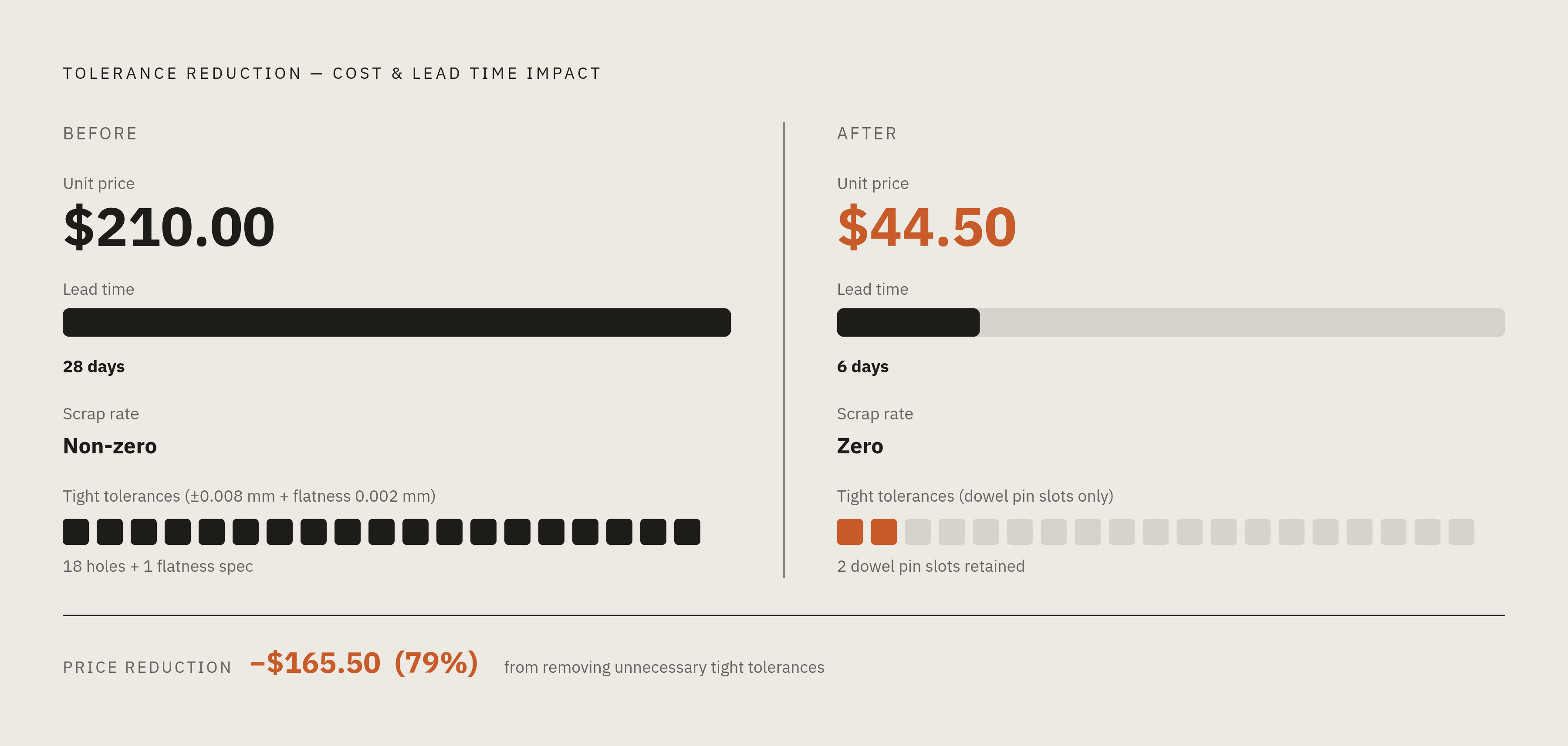
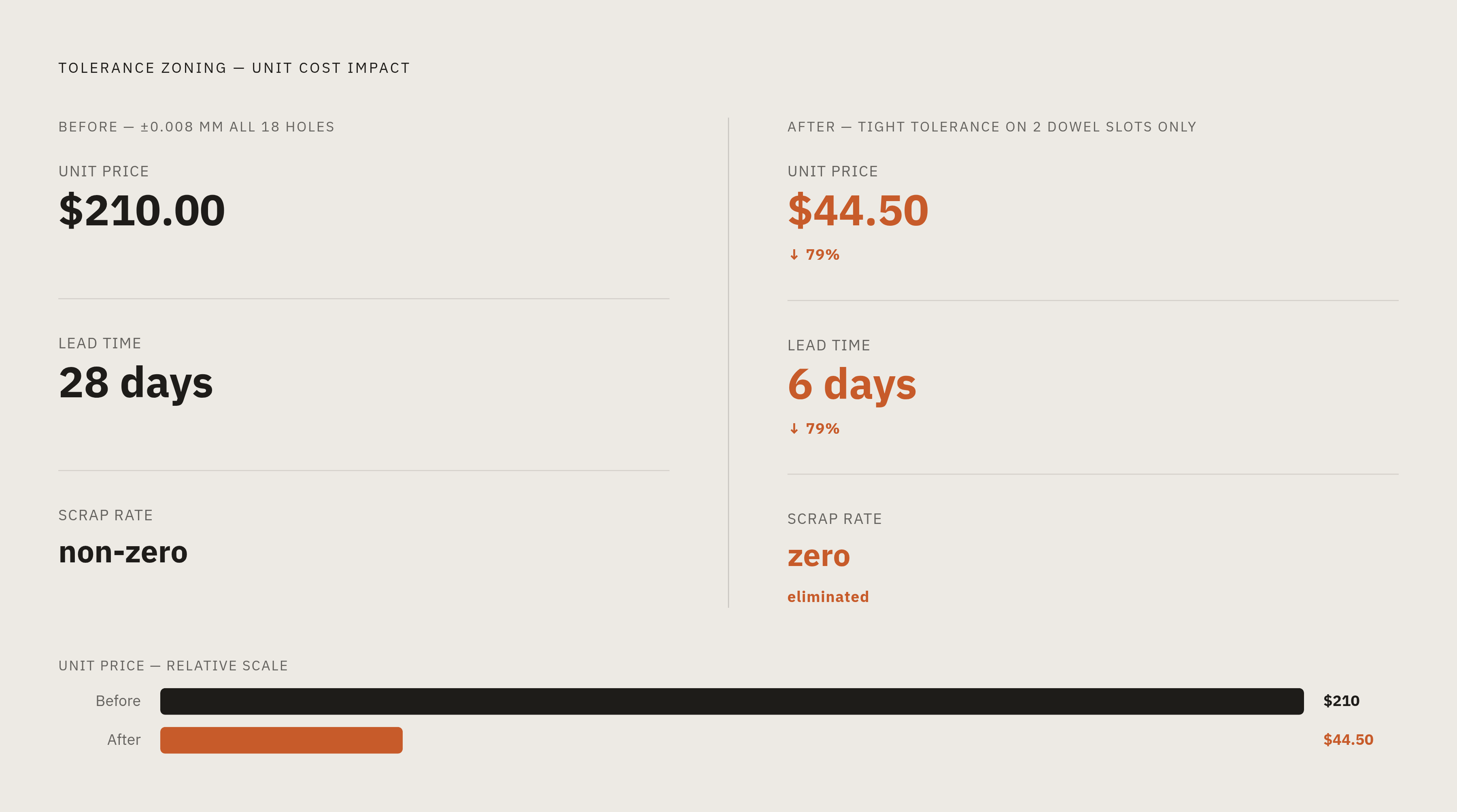
A DFM audit on one part found 14 of 18 holes were plain clearance passages for M6 screws, yet the drawing called for ±0.008 mm on every single one, on top of a flatness spec of 0.002 mm across a 400 mm plate of cold-rolled aluminum. That flatness number wasn't just expensive, it was physically at odds with the residual stress already baked into cold-rolled stock. Once the drawing got revised to reserve tight tolerances for the two dowel pin slots that actually needed them, unit price dropped from $210.00 to $44.50, scrap rate went to zero, and lead time fell from 28 days to 6.
That's not a rounding error. That's the cost of a template tolerance applied without thinking.
For low-volume prototype runs, tightening tolerance can substantially increase your cost and setup complexity, and that cost compounds every time you iterate the design. So if you're still changing geometry, hold standard tolerances everywhere and save the tight-tolerance drawing for the pre-production build, once the design is actually frozen.
Worth knowing, even if it rarely shows up on a prototype quote: aluminum starts losing strength above 200°C, and aggressive cuts on already-stressed stock generate real heat. Parts that need tolerances tighter than about 0.01 mm sometimes call for thermal stress relief between machining stages, baking at 175°C for 4 hours followed by furnace cooling at 20°C per hour. This isn't standard prototype practice, but if a quote comes back requesting it, that's why. And if you're chasing tight tolerances, 7075-T6 and 6061-T6 both hold dimensional stability better than softer alloys like 5052.
When 3-axis milling is sufficient and when the part actually needs 5-axis
Most aluminum prototypes never need 5-axis. Prismatic shapes, pockets, slots, holes, surfaces you can reach from the top or the four cardinal sides, that's standard 3-axis territory, and multiple 3-axis setups can chase down almost any feature given enough time. The cost shows up in that word: time. Every setup adds to it.
5-axis earns its cost when features sit on multiple non-parallel faces, or when the part carries compound angles and undercuts a 3-axis tool can't reach without repositioning the part over and over. A part that would need multiple separate 3-axis setups, each with its own repositioning and re-indicating, can sometimes run in a single 5-axis setup instead. On low-volume prototype jobs, where setup cost eats up a large share of the total price per part, that setup reduction can offset 5-axis's higher hourly machine rate. Freeform surfaces, compound angles, undercuts, these often come out cheaper on 5-axis overall, even though the per-hour rate is higher.
Lead time follows the complexity. Simple 5-axis geometry typically runs 2 to 3 days. Complex simultaneous 5-axis work, impellers, freeform surfaces, that kind of thing, runs 3 to 5 days. The bottleneck isn't the machine, it's the programming. A complicated 5-axis impeller toolpath can take 3 to 4 hours just to write and verify, and that's engineering time on the invoice, not machine time.
So count your machining faces before you submit anything. Say so in the RFQ if the part needs more than two. Don't assume the shop will route it to 5-axis on its own; if you describe complex geometry without flagging it, you may get back a 3-axis quote loaded with fixturing costs that end up costing more than 5-axis would have in the first place.
And sometimes milling isn't even the right process. Rotational features are often better suited to turning than milling. Very fine features or geometry that milling cannot reach cleanly may call for alternative processes. Flag these early so the quote reflects the actual process chain, not just the one everyone defaults to.
Surface finish and anodizing decisions that need to be made before the file is submitted
As-machined is a legitimate finish, and for a lot of prototypes, it's the right one. Aluminum straight off the mill is adequate for most mechanical and structural testing. Specifying a finish adds cost and adds lead time, so don't add one just because it looks more finished on paper.
When corrosion protection or appearance actually matters, Type II anodize is the standard choice for corrosion protection and appearance. When the surface needs to survive sliding contact or repeated wear, Type III hard anodize is the answer, but it adds coating thickness on every anodized surface, and that growth has to be accounted for wherever tight tolerances apply. The shop needs to know up front if a part is going to be anodized to a functional dimension, so they can leave extra machining stock on those surfaces before the coating goes on.
Alodine, a chemical conversion coating, is much thinner than anodize and doesn't meaningfully change dimensions. It's a good call when you need corrosion protection alongside tight tolerances, but it's not a wear solution, don't reach for it if the part needs to resist abrasion.
Before you submit the file, the drawing needs to say, in plain language, what finish you want: "Anodize Type II, Black per MIL-A-8625" or simply "As machined." Any surface that has to stay bare metal, threaded holes, precision bores, tight-tolerance mating faces, needs to be called out and dimensioned so it gets masked before coating. And if a surface has a functional roughness requirement, a sealing face or a bearing seat, spec the Ra directly; most prototype surfaces don't need it, but the ones that mate under pressure or motion do.
One more thing worth knowing before you pick your alloy: 7075 anodizes less evenly than 6061, so if a clean, consistent anodized look matters, 6061 is the better substrate. 2024 is generally a poor candidate for anodizing and is rarely finished this way.
What a complete file package includes when submitting for quote
Two files, every time: a 3D STEP file and a 2D PDF drawing. The STEP file gives the shop the geometry to program the machine from. The PDF drawing carries the dimensions, tolerances, finish callouts, and notes, the STEP file alone can't carry any of that. Check the two against each other before you hit submit, since the drawing wins if they ever disagree.
The title block needs to carry a specific set of information, and skipping any of it is one of the fastest ways to slow down a quote:
- Material and temper, written out fully: "6061-T6 Aluminum," not "aluminum"
- Finish, spelled out: "Anodize Type II, Black" or "As machined"
- Part number and revision letter. Every drawing needs both; without a rev letter, there's no way to track which version you're actually quoting as the design changes
- Units and drawing scale, clearly marked
- Projection standard: noted on the sheet so the shop knows which convention applies
- A general tolerance block that sets the default, so you only need to call out overrides on the features that actually require them
Beyond the title block, put critical tolerances directly on the drawing using GD&T or explicit dimension callouts, not buried in a note somewhere. Ambiguity is what turns a same-day quote into a week of back-and-forth email. The file package is the last chance to say exactly what you mean before someone else has to guess.