Surface Finish Options for CNC Aluminum Parts and Their Trade-Offs
Choose the finish based on function, not looks, or pay for rework.
Every finish on a CNC aluminum part changes something you can measure: dimensions, hardness, corrosion life, conductivity, cost. Pick the finish without knowing those trade-offs, and you find out the hard way, usually at assembly, when a plated bore won't take the mating shaft or an anodized ground plane won't pass continuity.
Type II anodize grows roughly 0.0002" to 0.001" per surface, splitting about half into the metal and half out, so toleranced features need a machining allowance but the change is predictable. Type III hardcoat is thicker, typically up to 0.002" total, with the same half-in half-out rule, meaning a 0.002" spec adds about 0.001" of dimensional growth per surface; both anodic processes are electrical insulators, so grounding surfaces and RF contact points must be masked or handled another way. Chem film (Alodine) adds no measurable dimensional change and keeps full electrical conductivity intact, which is why it is the standard call for EMI ground planes, close-tolerance fasteners, and structural aerospace parts in 2024 and 7075 where Type III is not viable. Electroless nickel deposits a uniform nickel-phosphorus layer across complex geometry, including internal bores and blind holes, building thickness that must be accounted for on mating features, and it is not a conductor enhancement the way chem film is but rather a wear-surface treatment that makes aluminum behave like a harder metal at the cost of added coating thickness and a higher per-part price.
Too many drawings treat finish as an afterthought, something chosen for looks or picked by default because it's what the shop always runs. That habit causes rejected parts and rework that costs more than the finish itself. More engineering teams are pushing aluminum into harder jobs than it used to see, and the finish has to hold up its end of that bargain.
Before you specify anything, answer three questions. What does this surface actually do in the assembly? What's the tightest tolerance on any feature the finish will touch? What environment does the part have to survive? Get those answers first, then pick from as-machined, bead blast, Type II or Type III anodize, powder coat, chem film, or electroless nickel. Each does a different job and costs a different amount. Most people pick the wrong one because they choose on looks instead of function. If you take one thing from this piece, take that: looks should be the last question you ask, not the first.
How Ra values translate into real part behavior — and real cost
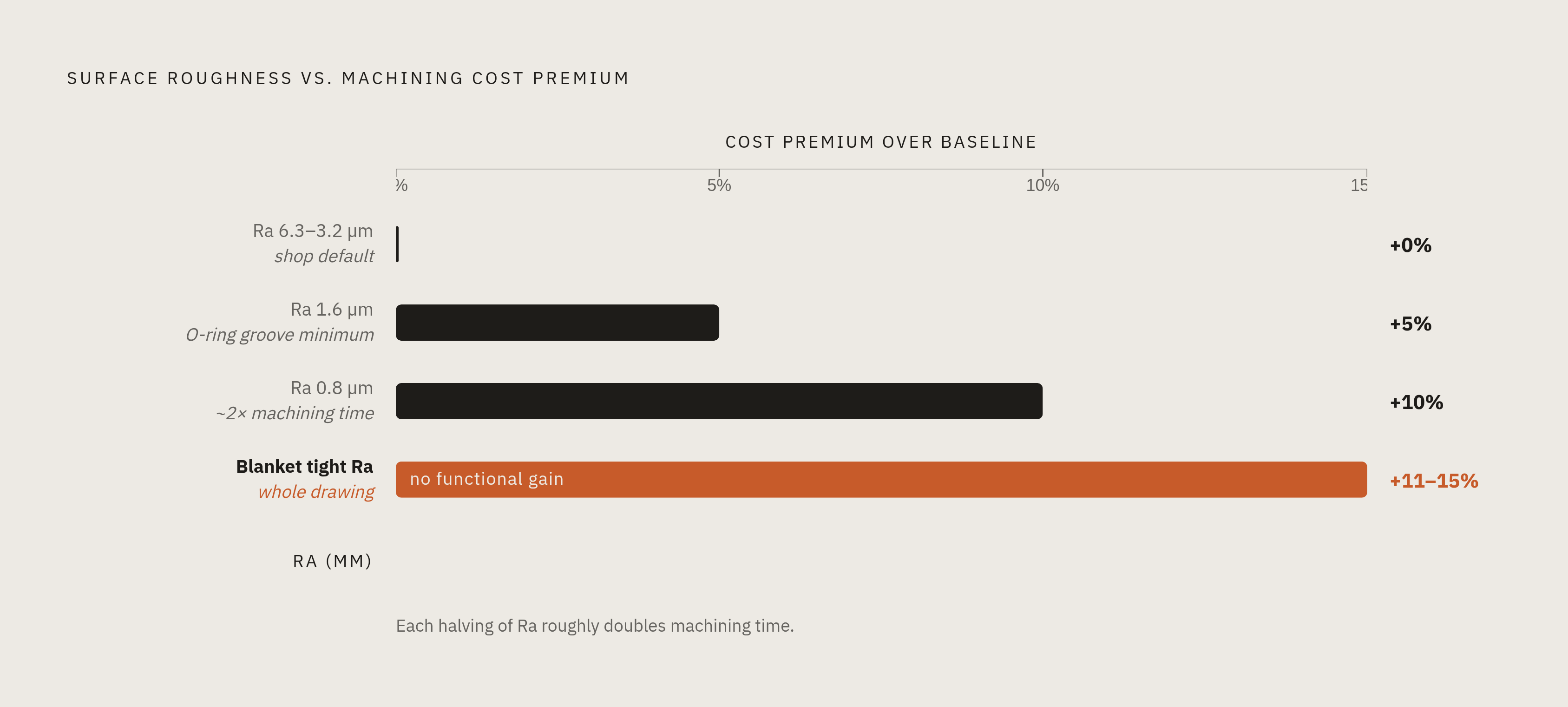
Ra, arithmetic mean roughness, is the number that shows up on drawings and in shop quotes. It's the average height of the peaks and valleys on a machined surface, and it's the term everyone on the floor actually says out loud when they talk about finish.
A few thresholds matter more than the rest. Ra 3.2 μm, or 125 microinches, is the standard as-machined default in most shops and works fine for structural features that don't seal or mate against anything. Drop to Ra 1.6 μm or smoother at an O-ring groove, because anything rougher opens a leak path; that's not a cosmetic call, it's a functional one. General structural surfaces sit comfortably in the Ra 3.2 to 6.3 μm range with zero performance penalty. Optical surfaces or ultra-precise seals can go down to Ra 0.05 to 0.2 μm with polishing, though you pay for it.
And you pay a lot. Each time you cut the Ra spec in half, total machining time roughly doubles once you count setup, tool changes, and inspection — a compounding effect that makes tight Ra specs expensive fast. A finer-than-default finish typically adds about 5% to the price on standard alloys with simple geometry, more if the part's complex. Push for the tightest Ra call-outs across the board and you're looking at 11% to 15% on top of baseline cost. One part I've seen had 80% of its surfaces sitting at a functional Ra 6.3 μm with zero need for anything tighter; a blanket tight spec across the whole drawing doubled the manufacturing cost for no functional gain.
Here's the fix. Zone the drawing. Call out tight Ra only where a surface does real work: mating, sealing, sliding. Let everything else run at shop default. Most engineers who blanket a drawing in a tight Ra call-out are doing it out of caution, not need, and they pay double for that caution when a five-minute look at the print would've told them which surfaces actually matter. For reference, CNC milling lands you in Ra 0.8 to 6.3 μm, turning in 0.8 to 3.2 μm, grinding in 0.2 to 1.6 μm. 6061 with standard carbide tooling hits Ra 1.6 to 3.2 μm without anyone trying hard.
As-machined finish: when leaving aluminum alone is the right call
As-machined means the part ships exactly as the mill or lathe left it. Tool marks stay visible, no secondary step touches the surface, and Ra lands somewhere between 0.2 and 3.2 µm depending on toolpath, speed, and feed rate.
This is the right call for internal structural parts with no appearance requirement, for parts headed into a later finishing step that doesn't need an intermediate treatment, and for early prototype runs where dimensional accuracy matters more than surface protection. It's also the answer whenever a coating would mess with thread fit or press-fit tolerance, since coatings add thickness and threads don't have room to spare.
It has real limits, though. Bare aluminum forms a thin native oxide layer fast, which gives some passivation but nowhere near the corrosion resistance you'd want in a wet or harsh environment. There's no wear resistance at sliding or contact surfaces. And tool marks trap contaminants, which matters a lot in food, medical, or cleanroom work.
6061 machines cleanly to Ra 1.6 to 3.2 μm with standard tooling, which is why it's among the go-to alloys whenever as-machined is acceptable. The real failure mode here runs in both directions. One engineer leaves finish unspecified and hopes the shop picks something sensible; another blankets the whole drawing in Ra 1.6 μm just to feel safe. The first causes ambiguity on the floor. The second pays for precision nobody asked for.
Bead blasting: what it does and doesn't fix
Bead blasting fires fine glass or ceramic media at the part under pressure, leaving a uniform matte texture, usually Ra 0.8 to 3.2 μm, that repeats consistently across a production batch.
What it actually buys you: it hides tool marks and witness lines from machining, gives complex geometry a clean, consistent look, and preps the surface for anodizing, which is why it shows up in process sequences as often as it does.
What it doesn't buy you is protection, and this is where people get confused. Bare, bead-blasted aluminum still oxidizes and discolors over time with nothing standing between it and moisture. It adds no hardness at all. What it does give you is zero dimensional penalty, one place it beats anodize and plating outright, since neither the part's size nor its tolerances shift.
The trap is treating a cosmetic and prep step like a functional finish. Blast a toleranced bore, an O-ring groove, or a mating face, and the texture variation can wreck sealing or fit. Mask those features before blasting, or handle them in a separate operation afterward.
Bead blast on its own makes sense for aluminum going into controlled indoor settings: consumer electronics housings, instrument enclosures, anywhere oxidation risk stays low and a consistent look across the batch matters more than corrosion life. Blast first to erase tool marks, then anodize; that sequence produces the clean, uniform surface you see on a lot of electronics enclosures and optical housings, and I'd default to it every time bead blast alone is on the table as a "finish." Bead blast by itself, with nothing after it, is a look, not a finish.
Anodizing Type II vs. Type III: the same electrochemical process, very different outcomes
Anodizing converts the surface of the aluminum itself into a dense oxide layer. It grows out of the base metal rather than sitting on top of it, which is exactly why the dimensional change is predictable and can be engineered around instead of just tolerated.
Type II, the sulfuric process, gives standard corrosion protection and a moderate bump in hardness over bare aluminum. Color range is wide: black, red, blue, gold, clear, all reliable through dye. Ra after the process typically sits at 0.4 to 1.6 μm. One thing Type II can't do is white; the oxide layer is transparent and won't hold white dye reliably, so you get a dull grey instead. It's the right fit for cosmetic and moderate-duty work, consumer and commercial hardware, anything needing color-coded identification.
Type III, hardcoat anodize, builds a much thicker, denser layer aimed at wear resistance and surface hardness rather than looks. Color options shrink to black or dark grey, full stop, and if you need anything else, Type III is the wrong choice from the start. The dimensional rule here matters more than almost anything else in this piece: about half the coating thickness eats into the part and half builds up on the surface. A typical 0.002" thickness spec means roughly 0.001" of dimensional growth per surface. Machinists have to cut the part undersize on mating and tolerance-critical features to account for that growth, or the part fails inspection outright. Type III belongs on aerospace components, wear surfaces, sliding interfaces, hydraulic parts: anywhere surface hardness carries load rather than just looking good.
Alloy choice isn't flexible here. 6061 and 6063 anodize well for corrosion protection and appearance, which is why they're the default whenever anodize is the target. Per MIL-A-8625F, Type III generally can't go on alloys with copper content above 5% or silicon above 8%, which rules out most die-cast alloys like A380 and limits how far you can push 2024. For 2024 and 7075, chemical conversion coating or Alodine is the reliable path to corrosion protection instead. Forcing Type III onto those alloys is a specification error that will produce poor results and should be caught at the design review stage.
One more constraint worth remembering: every anodic coating is an electrical insulator. Grounding surfaces, RF contact points, anything that needs to carry current has to be masked off or treated another way. On Type II parts, a small post-op reaming allowance on precision bores usually beats trying to mask them cleanly.
Powder coating: where it outperforms anodize and where it doesn't
Powder coat sprays on electrostatically and cures under heat into a continuous polymer film. Unlike anodize, this layer sits on top of the metal rather than growing out of it.
Where it wins: color range beats anodize by a wide margin. True white, textured finishes, high gloss, all on the table. Impact resistance is strong, good for enclosures and covers that take physical abuse. It also works on alloys anodize can't touch, A380 die-cast aluminum in particular, where the surface comes off the mold at Ra 6.3 to 12.5 µm and powder coat smooths and seals those casting imperfections in one step. That makes powder coat the practical default for die-cast parts, full stop, and it's cost-competitive on small to medium runs too.
Where anodize wins instead: the coating layer is thicker and less consistent, so toleranced holes, threads, and mating surfaces need masking or cleanup afterward to keep fit intact. Powder coat can chip at edges and corners over time, something integral, grown-in-place anodize doesn't do. And it's a poor fit for thin-wall or high-precision features, since the coating buildup eats into clearance.
A few design rules follow from this. Mask every threaded hole before coating, since cutting thread relief afterward is hard and tears up the finish. Build in extra clearance at mating features from the start if powder coat is the plan. Call out an edge break on sharp corners too, because powder coat doesn't hold on sharp edges reliably and tends to thin out right where you need it most.
What are the dimensional and conductivity trade-offs of chem film versus anodize and electroless nickel on aluminum parts?
Chem film, often called Alodine after the trade name, works through a chemical reaction that deposits a thin chromate or trivalent-chromium film on the surface. It's a conversion, the same basic idea as anodize, just without the thickness, so nothing gets added on top.
The trade-off in one line: less hardness and wear resistance than anodize, but no measurable dimensional change and full electrical conductivity kept intact.
That makes it the right call for RF and EMI ground planes, anywhere a surface needs to stay conductive and still get some corrosion protection. It's also right for fasteners, brackets, and small hardware where even 0.001" of coating growth would throw off fit. Parts headed for paint or adhesive bonding do well with chem film too, since it makes an excellent primer for both. On cost, chem film runs cheaper than anodizing across the board. If a part doesn't need hardness, paying for anodize anyway is money wasted.
MIL-DTL-5541 Class 3 is the spec to call out for low electrical resistance work, worth flagging explicitly on any aerospace or defense drawing. On alloy fit, 2024 and 7075, both poor candidates for Type III anodize, respond well to chem film, which is why it's the standard corrosion treatment for high-strength aluminum in structural aerospace parts.
One regulatory note worth flagging: hexavalent chromium is facing tighter restriction under RoHS and REACH, and trivalent chromium alternatives are becoming the standard replacement. Specify which one you'll accept up front, or you risk a supply chain delay later.
The decision rule is straightforward. Pick anodize when hardness and durability come first, and pick Alodine when conductivity, minimal dimensional change, and cost come first. Don't split the difference; the two finishes solve different problems, and a part that tries to get both usually gets neither.
Electroless nickel plating: when aluminum needs to perform like a harder metal
Electroless nickel plating deposits a nickel-phosphorus layer through an autocatalytic chemical reaction rather than an electric current. That's what lets it coat a part evenly across complex geometry, recessed features, internal bores, and blind holes, places electroplating struggles to reach at all. The result behaves less like plated aluminum and more like a hardened steel surface bonded to a much lighter part, which is exactly the point when a design needs aluminum's weight with a wear surface aluminum alone can't provide.