GD&T Callouts That CNC Machinists Can Actually Inspect
Design and shop floor must agree on how to measure each tolerance, or rework and disputes follow.
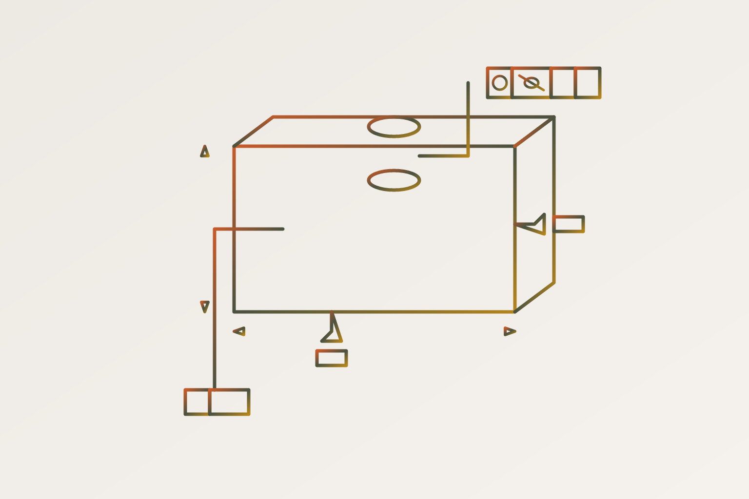
A GD&T callout only means something if a machinist can actually measure it. Drop a tight true position or an over-specified profile tolerance on a print without thinking through inspection, and the shop is left guessing, which turns into rework, scrap, or an argument over whether a part should have been rejected in the first place. This piece walks through the symbols, datum structures, and material modifiers that hold up on a CMM or under a hand gauge, and where drawings quietly create dead ends.
Here's a test worth running on any callout before it leaves the drawing: can it be explained, in a sentence or two, how it gets measured? If not, it needs work. That's not a knowledge gap between design and the shop floor. It's a translation problem, and it's fixable at the drawing stage.
How the governing standard shapes what the shop floor can verify
Two standards run the world of geometric tolerancing: ASME Y14.5-2018, which dominates in North America, and ISO 1101:2017, which governs most everywhere else. They don't just use different symbols in a few edge cases. They disagree on fundamentals.
ASME defaults to RFS (regardless of feature size) across the board for geometric controls. ISO runs on something called the Independency Principle, where each tolerance stands alone unless a relationship is spelled out explicitly. That's the opposite default logic. ASME ties size and form together; ISO treats them as separate questions unless told otherwise. That's a long way from the old assumption that the two systems basically agreed.
Concentricity is where this bites hardest. It's still a valid control under ISO 1101. Under ASME Y14.5-2018, it's gone, removed from the standard entirely. Yet plenty of older drawings still carry a concentricity callout, sitting in production files, getting pulled and re-run years after they were drafted. Inspect those as drawn, and there's real ambiguity about what "as drawn" even means anymore.
There's a downstream effect on tooling, too. ASME-style drawings tend to assume hard gaging, pins, rings, thread gages. ISO-style drawings lean toward CMM-based inspection. Specify the wrong standard for a given supply chain, and the shop may be tooled up for a measurement method the drawing never anticipated.
The fix costs one line. Put "DIMENSIONING AND TOLERANCING PER ASME Y14.5-2018" (or the ISO equivalent) in the title block or general notes, on every drawing, no exceptions. That single sentence resolves most standard-mismatch disputes before a part ever reaches an inspector.
The GD&T symbols that map most directly to real inspection methods
Flatness is the cleanest control on the print. No datum, period. If a flatness callout shows up with a datum reference attached, that's a drafting error, not a design choice. It matters most on sheet metal and weldments, where forming and welding warp a surface long after the drawing said it was flat. A flatness callout on a mounting face is what keeps that face seating and sealing correctly. Inspection is about as simple as GD&T gets: surface plate and height gauge, CMM, or a laser scanner. Worth noting, material behavior belongs in the tolerance decision. Wrought aluminum like 5000-series warps more than a cast plate like MIC6, so a flatness spec should account for how the material actually moves, not just what the function needs.
True position carries the most weight in CNC hole-making, and it's also where a badly specified callout can sink an entire assembly even though every hole measures in spec individually. Basic dimensions pin down the nominal location; the geometric tolerance defines the allowed wobble around it, evaluated as one cylindrical zone rather than separate X and Y numbers. That cylindrical zone is worth understanding on its own: a ±0.005 in. X/Y tolerance produces a square tolerance zone, but the functionally equivalent position callout gives a circular zone with 57% more usable area. Same fit requirement, more parts that pass. For inspection, CMM covers prototypes and small batches well; functional go/no-go gauges take over once volumes hit 50 parts or more.
Perpendicularity earns its keep on stacked assemblies. Unlike form controls, it needs a datum, since it's describing a 90-degree relationship to something. A perpendicularity callout on a threaded hole is what keeps a fastener from cross-threading or losing preload, problems that often don't show up until final assembly. Inspection runs through CMM, a precision square, a height gauge, or a functional gauge built for the thread. One mistake shows up constantly: perpendicularity added to a threaded hole without saying whether it controls the thread axis or the counterbore. That's a decision the machinist shouldn't have to make alone.
Profile of a surface does more work than any other symbol on the list. Without datums, it controls form only. Add datums, and it controls form, orientation, and location all at once, replacing what would otherwise take three or four separate callouts. That's part of why profile shows up so often on 5-axis parts and freeform geometry now. It's the one control that lets a CNC shop hold tolerance on shapes that casting or stamping never could. Inspection means CMM with 3D scanning or a direct CAD comparison, which means the inspector needs the CAD model in hand. That's a detail that belongs in the quoting conversation, not something to sort out after the part is cut.
Runout is non-negotiable on anything that spins. Circular runout checks each cross-section as the part rotates around a datum axis, typically read with a dial indicator. Gears, turbines, medical drill shafts, none of them tolerate runout that can't be checked in the fixturing available. If a runout callout can't be inspected on the equipment at hand, that's a design problem, and it needs to get fixed before the part is cut, not argued about after. Worth repeating: concentricity is gone under ASME Y14.5-2018. Runout or position controls are what a compliant drawing uses instead.
Form controls, flatness, straightness, circularity, cylindricity, are all self-contained. None of them take a datum reference, ever. Cylindricity costs the most to check because it demands roundness testing and axial scanning at the same time, so it belongs on precision shafts and hydraulic rods where the full 3D envelope actually matters, not on parts where a simpler control would do.
How material condition modifiers, MMC, LMC, and RFS, change what the shop actually measures
Modifiers do more good, and more damage, than almost anything else in GD&T. Misapplied, they reject parts that function perfectly fine, not because the part failed, but because someone evaluated the tolerance at the wrong condition.
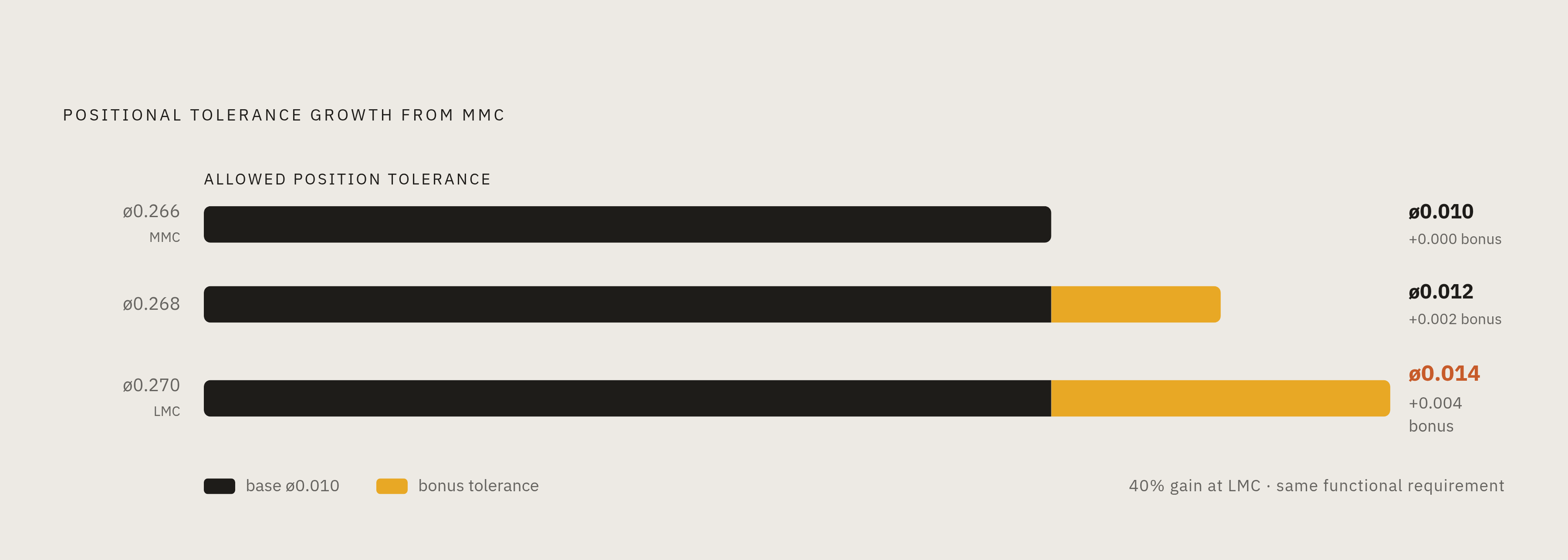
MMC is the workhorse for hole patterns. It lets a feature earn extra positional tolerance as it drifts from its maximum material condition, which cuts rejection rates without giving up anything on assembly. Take a hole sized between ø0.266 and ø0.270 in., with a position callout of ø0.010 in. at MMC. Machine that hole out at ø0.270 in., away from MMC, and it picks up 0.004 in. of bonus tolerance, bringing the allowed position out to ø0.014 in. Same fit, more parts accepted. For an internal feature at MMC, the virtual condition, the number a functional gauge gets built around, equals the MMC size minus the geometric tolerance. One thing to keep straight: bonus tolerance never applies to form controls, and it doesn't apply to anything left at RFS. Slapping a material modifier onto controls where it doesn't belong is a drafting mistake waiting to cause a fight during inspection.
Functional gauging is where MMC really earns its keep in production. A go/no-go gauge checks position at MMC without any coordinate measurement at all: hardened pins sit at the nominal true positions, each cut to the virtual condition diameter, and if the part drops over all the pins at once, every hole passes. That's typically 5 to 10 times faster than running the same part through a CMM, and it doesn't need a skilled operator standing over it. For production runs of 50 parts or more, that's the default choice. It won't replace a CMM when the drawing calls for individual recorded measurements, but for a pass/fail production check, nothing beats it on speed.
LMC shows up less often, and for good reason. It matters when the functional risk is running out of material, not clearance, thin walls, edge distances, features where cutting away too much compromises strength. Castings and thin-walled housings are where LMC earns its place; most general machined parts never need it.
RFS is the default under ASME Y14.5-2018, no modifier symbol required, but no bonus tolerance either. Pick it when the function demands tight control of size and geometry together, regardless of clearance, an alignment pin hole on an optical mount is a good example, where even a small shift throws off alignment and there's no room to trade tolerance for material condition. RFS always means CMM or coordinate measurement. A functional gauge is built to one fixed virtual condition and is not suited to checking features evaluated regardless of size.
Datum selection, the single biggest source of inspection failure on the shop floor
Most tolerance disputes don't come from tolerances that are too tight. They come from a datum structure that never reflected how the part actually functions, parts that measure fine and still don't assemble right.
Datum order isn't a formality. The primary datum locks down the most degrees of freedom, the secondary adds more, the tertiary picks up what's left, and changing that order changes the entire measurement setup. Treating all three as equally weighted is one of the more common errors on the inspection side. A CMM operator who sets up the datum precedence wrong will get results that are invalid, no matter how accurate the machine is.
A few mistakes come up again and again. Picking a datum feature that wobbles or doesn't repeat part to part, chosen because it was easy to call out on the drawing rather than because it's stable. Choosing a datum that doesn't match how the part actually sits in its fixture during machining, so the reference used for measurement never lines up with the reference used to cut the part. And there's a process mismatch to watch for, too: Pick a datum that fights the dominant machining process, and setup complexity climbs along with inspection risk.
A workable rule: choose the surface the part actually seats on in assembly as the primary datum, as long as it's machined, flatness-controlled, and big enough to hold the part steady. An unstable cast face, or a tiny pad chosen for convenience, guarantees inspection results that won't repeat from part to part.
Large or flexible parts need extra thought. Pick datums less likely to distort under their own weight or during handling, especially for thin-walled parts. Large parts often need multiple machining setups, so it can help to break tolerances into zones, each referencing the datums actually accessible in that setup. Material choice belongs in this conversation too: wrought aluminum like 5000-series warps more readily than a cast plate like MIC6, and on a long CNC part with tight tolerance, part geometry and fixturing choices that reduce distortion help keep datum surfaces stable after machining.
None of this matters if the CMM program doesn't mirror the datum structure on the print, in the same precedence order. Get that wrong, and every inspection result off that program is invalid, regardless of how good the machine is.
What the shop floor can actually reach: probe access, inspection tools, and the decisions that must happen at the drawing stage
CMM inspection is the standard for machined metal parts. A tactile probe checks position, diameter, depth, and geometric relationships against the datum structure on the print. But a probe can only measure what it can physically reach, and that's a limit worth respecting at the drawing stage, not discovering after the part is already cut.
Deep pockets, small blind holes, undercuts, re-entrant features, all of these can carry real geometric importance and still sit completely out of reach for a standard probe. If a feature can't be reached, the options are limited: open the geometry so the probe can get in, accept a different inspection method like optical measurement or a dedicated gauge, or spell out that alternate method on the drawing itself so nobody's guessing later.
Matching the method to the callout comes down to volume and complexity, mostly. True position on hole patterns runs through CMM for prototypes and complicated patterns, and shifts to functional gauging, 5 to 10 times faster per part, once production quantities climb. Profile tolerances on complex 5-axis geometry need CMM scanning against the CAD model, full stop, there's no hard-gage substitute for freeform surfaces. Flatness and the other form controls stay simple: surface plate work or CMM, no datum complications to sort through. Runout needs a dial indicator and a fixture that actually holds the datum axis the way the print assumes.
None of this is a shop-floor problem to solve after the fact. It's a drawing-stage decision, and the earlier it gets made, the fewer disputes there are about what a callout actually meant.