Die Casting vs CNC Machining for Mid-Volume Aluminum Parts
Cutting tooling cost and material strength reveal which process wins for mid-volume aluminum runs.
What each process does to aluminum, and why the physics matter for the decision
For mid-volume aluminum parts, somewhere between a few hundred and a few thousand units, the die casting versus CNC machining decision gets expensive precisely because it isn't obvious. At the extremes, nobody argues: a dozen prototype brackets go on a CNC mill, a large batch of identical housings goes to a die caster. The trouble sits in the middle, where teams either sink capital into tooling for a part that never hits scale, or grind out thousands of machined parts at a per-unit cost that quietly bleeds margin for years. Most teams pick based on whichever factor is loudest that week, tolerance, timeline, or sticker shock on a quote, instead of weighing tooling amortization, tolerance ceilings, and design maturity as one decision. That habit is the actual root cause behind most bad calls in this range, not any flaw in either process itself.
CNC machining is subtractive. A cutting tool removes material from a solid block of wrought aluminum, usually 6061 or 7075, until what's left is the part. No mold, no melt, no injection. Tolerances land routinely at ±0.01 mm, and a precision setup holds ±0.005 mm. The tradeoff is waste: 60 to 80% of that billet ends up as chips on the shop floor. But since there's no tooling standing between the CAD file and the part, the first unit off the machine costs the same as the ten-thousandth.
Die casting works the opposite way. Molten aluminum, usually A380, ADC12, or AlSi9Cu3, gets injected into a hardened steel mold at speeds pushing past 5 meters per second. Once the die is running, a cycle takes 30 to 90 seconds, and cost per part falls off a cliff as volume climbs. Surface finish is in the Ra 1.6 to 6.3 μm range, rougher than a machined face but a lot cleaner than sand casting.
Die cast alloys earn their spot because they flow well into a mold and fill thin sections without tearing. That fast fill comes at a price: rapid solidification traps gas and shrinkage voids inside the casting, and that internal defect structure can cut strength by 10 to 30% compared to machined wrought stock. For a cosmetic housing, that's irrelevant. For a bracket carrying fatigue load, it's the whole ballgame. Picking die casting for that bracket on cost alone is a mistake that appears months later as a warranty claim, not a mistake anyone catches at the quoting stage.
These processes aren't two roads to the same destination. They carry different cost structures, different strength ceilings, and different design rules baked in from the start. Picking one really means figuring out which of those constraints governs the part sitting in front of you.
How tooling cost amortizes across a production run
Die casting tooling runs anywhere from $8,000 to well over $150,000, depending on cavity count, part complexity, and any slides or side-actions the die needs to pull off undercuts. CNC tooling cost, by comparison, is basically zero, which is the whole reason the two processes get compared as if they're interchangeable when they aren't.
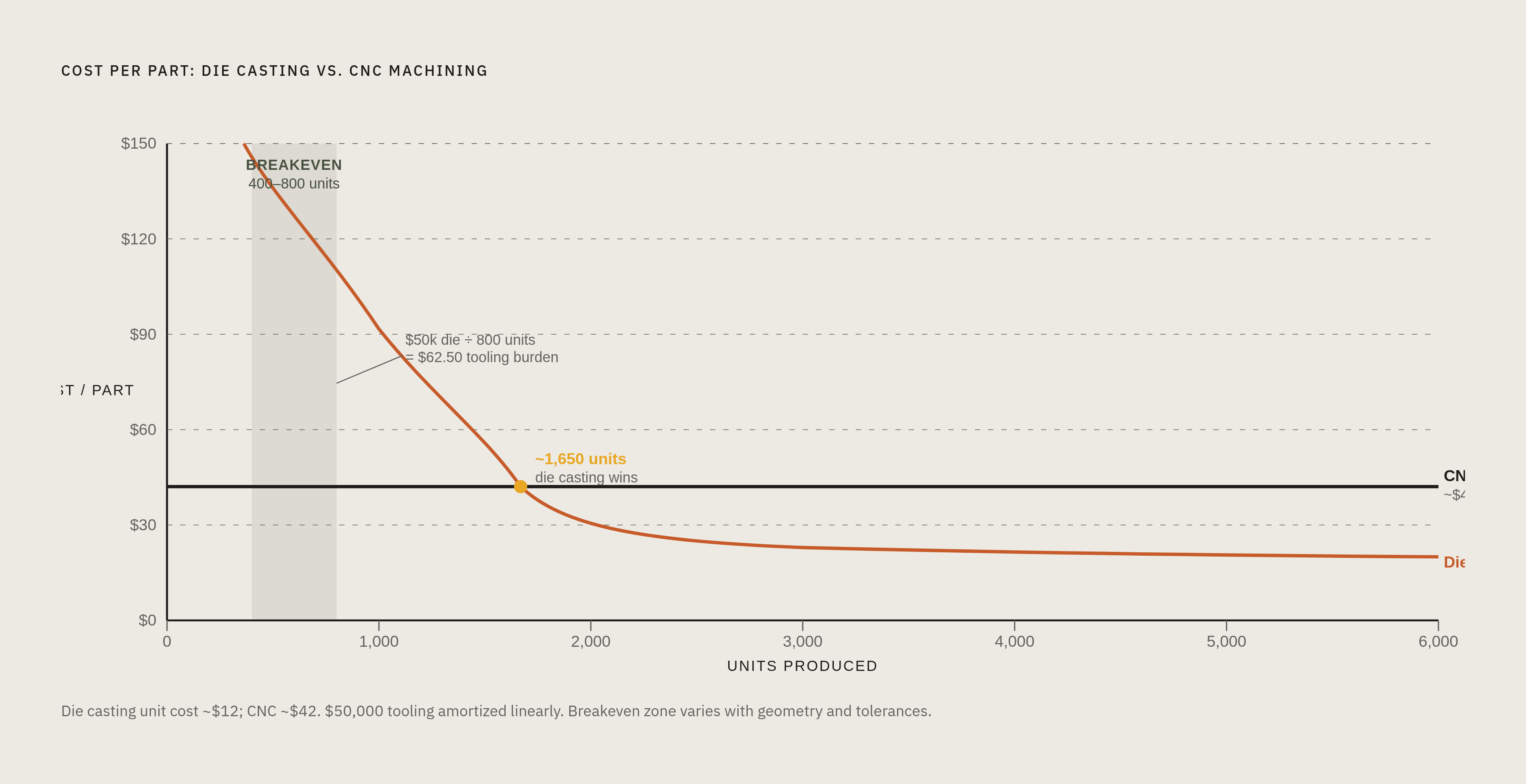
Run the math on a mid-size die: $50,000 spread across a 1,500-unit lifetime adds $33 to every part before material, labor, or machine time gets counted. That number anchors every breakeven conversation that follows. Simple geometries can break even against CNC as low as 400 to 800 pieces, which surprises people who assume die casting only makes sense at huge volumes.
Tooling isn't a one-time expense either. Budget 5 to 10% of the original die cost every year for maintenance. A well-kept aluminum die is good for 80,000 to 150,000 shots, and even in steady production, scrap rates typically run 3 to 8%. None of that is visible in the initial quote, but all of it appears in the final cost per part. Anyone comparing die casting to CNC using the tooling quote alone is comparing the wrong numbers, and the gap between those two comparisons is where most budget overruns hide.
Tolerance requirements and where each process hits its ceiling
CNC machining tops out at a tolerance most other processes can't touch: ±0.01 mm as a routine number, ±0.005 mm with a precision setup, surface finish down to Ra 0.4 µm when it matters.
Die casting, left as-cast, runs ±0.2 mm for small features, with the NADCA standard putting typical as-cast tolerance at ±0.15 to 0.25 mm. Fine for a housing wall or a mounting boss. Not fine for a bearing bore, an O-ring land, or any sealing face that actually has to seal.
That gap is why so many cast parts get a secondary CNC pass anyway. Flash and gate remnants have to be trimmed off every die cast part regardless of tolerance needs, so once a part is already headed for a machine, tightening the critical surfaces at the same time costs almost nothing extra. With that secondary step, ±0.05 to 0.10 mm becomes achievable on the features that need it. For anything with precision mating surfaces, the real choice was never die casting or CNC. It's die casting followed by CNC, run as one combined process from the start, and treating them as separate decisions is where the tolerance math goes wrong.
Draft angle trips up more programs than tolerance does. Die cast aluminum parts need 1° to 2° of draft to release from the mold cleanly, and that requirement reaches into internal geometry and deep pockets in a way CNC never has to think about. A CNC part can carry a dead-vertical wall with zero draft, no problem. A die cast part can't, not without adding a pull mechanism to the tool, and that mechanism adds cost and cycle time that rarely appears in the pitch for why die casting is cheaper.
Design stability and the cost of changing your mind after the die is cut
CNC machining forgives indecision. Changing the model regenerates the toolpaths and cuts the next revision. The whole loop takes days, and there's no sunk cost sitting in a steel block somewhere.
Die casting doesn't forgive much of anything. Once a die is cut, changing the part geometry usually means reworking the tool, and depending on where the change falls, that's a partial rebuild or a full replacement. Mold fabrication already takes 8 to 12 weeks, so a design flaw caught after the tool is ordered doesn't cost a few days. It costs a couple months and a chunk of the tooling budget. That's the trap that catches teams who commit to a die before the design has actually stopped moving, and it's an entirely avoidable one.
DFM for die casting has to happen before the purchase order goes out, not after the first parts come off the tool. Three things matter most:
- Wall thickness stays uniform, since thick sections cool slower than thin ones and that mismatch causes sink marks and warpage. Ribs add stiffness far more efficiently than thickening the wall ever will.
- Filling patterns and solidification rates get modeled ahead of time, so air entrapment and shrinkage appear in software instead of on the shop floor.
- Secondary operations can end up eating as much as 80% of a component's total cost, and when those operations are driven by avoidable defects, that's a budget nobody planned for, gone into rework.
Catching these on a screen is cheap. Catching them after the tool is cut is how a program ends up paying for corrections it never budgeted a dollar for.
Lead time as a decision variable, not just a delivery detail
CNC machining delivers parts in 3 to 7 days, with some shops turning simple geometries around in 1 to 5. Die casting takes 4 to 8 weeks for production parts once the tool exists, and mold fabrication itself eats another 8 to 12 weeks before that clock even starts.
For a program racing an NPI deadline, a customer commitment, or a trade show date, that gap decides the process choice on its own, regardless of what the per-unit cost math says. A cheaper part that arrives too late is still a missed date, just one with a smaller number attached to it.
The broader supply chain backdrop makes this worse. Structural bottlenecks elsewhere, memory components with lead times stretching past 58 weeks in some automotive categories, leave mechanical parts programs almost no room to absorb extra schedule risk from a die that arrives late or needs rework.
Lead time and design stability tangle together, too. A team that needs parts fast to validate a design can't afford to sit through 8 to 12 weeks for a die, only to find out afterward that the design needed to change anyway. Tooling committed before validation is one of the more expensive, and more common, ways these programs go sideways.
The extrusion hybrid as a third path for linear cross-sections
Parts with a constant cross-section running along one axis, enclosures, rails, structural frames, heatsink profiles, can skip the die casting versus CNC argument. Push a custom extrusion profile, then CNC-finish whatever critical features and fits the part needs.
Extrusion tooling costs land well below an HPDC die, and the die itself takes roughly 3 to 4 weeks to fabricate, a fraction of what an HPDC tool needs. The economic breakeven for extrusion plus secondary machining typically falls in the same hundreds-to-a-few-thousand range that defines the mid-volume gray zone. That overlap is the result of the same underlying economics. It's why this hybrid deserves a seat at the table before anyone defaults to die casting or straight CNC, and most teams never run the comparison because they don't know the option exists.
There's a cosmetic upside, too. The 6063 alloy commonly used in extrusion takes anodizing beautifully, producing a rich, streak-free satin finish that HPDC alloys can't match for color anodizing or hardcoat work.
The cross-section has to actually stay constant, though. The moment a part needs integrated bosses in multiple planes, complex 3D transitions, or thin-wall undercuts, extrusion is off the table, and the part goes back to being a conversation between the other two processes.
A variable-by-variable decision framework for mid-volume aluminum programs
Treat this as a sequence of filters. Some answers eliminate a process outright, and there's no point running the rest of the checklist once that happens.
Filter 1, lifetime volume. Under a few hundred parts, stay on CNC and skip the rest of the analysis; the tooling math never closes. At 400 to 800 parts with common aluminum alloys, run the actual breakeven numbers, because die casting might already win there. Between 2,000 and 5,000 parts, die casting is likely cost-competitive, so move to the next filter. Above 5,000 parts, die casting is the default unless something further down the list rules it out.
Filter 2, design stability. If the design hasn't been validated yet, stay on CNC and don't commit to tooling, full stop. Committing capital to a die before the design is frozen is how programs end up paying for a second tool. Once the design is frozen and has been through a proper DFM review for casting, the tooling investment is defensible, and not a day before that.
Filter 3, tolerance and finish. If every feature fits within ±0.2 mm as-cast, die casting alone might handle the whole part with no secondary work. If any critical feature needs tighter than ±0.1 mm, plan for secondary CNC regardless of which base process wins. And if hardcoat anodizing is a requirement, that rules out HPDC. Wrought stock, whether from CNC or extrusion, is the only path there.
DFM decisions that change the economics before a single chip is cut or die is ordered
The cheapest fix on any of these parts happens on a screen, before a chip is cut or a die is ordered, never on a shop floor after the fact.
Wall thickness has to stay uniform because thick sections cool slower than thin ones, and that mismatch is the direct cause of sink marks and warpage. Ribs stiffen a section far more efficiently than thickening the wall would, and they sidestep the cooling mismatch.
Draft angle is non-negotiable, too. Aluminum die cast parts typically require draft angles in the 1° to 2° range to release cleanly, and deep features need that draft designed in from the start, not discovered after the first shot comes out of the tool stuck fast. Every one of these calls is cheap to make in CAD and expensive to fix in steel. That asymmetry is the entire argument for running DFM before tooling gets committed, rather than letting the first bad shot make the case the hard way.