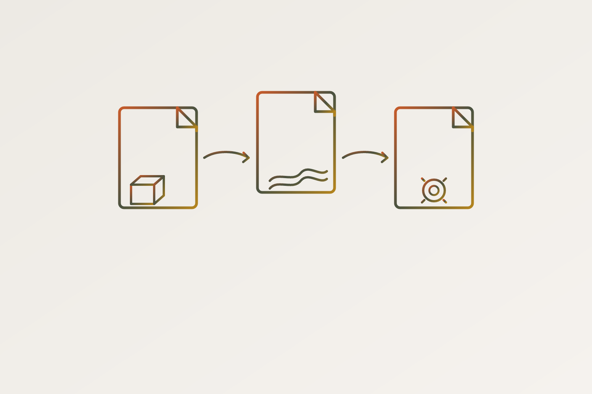
Drawing vs Model-Based Definition for Custom Part Orders
Choosing between 2D drawings and 3D models depends on shop capability.
Engineers ordering custom parts hit this decision constantly: send a 2D drawing, send a 3D model with embedded data, or send both. The friction is often basic: what engineers assume a shop can read and what the shop actually processes don't match up. A file sent in good faith sits unopened or gets misread, and the order stalls before a single cut is made.
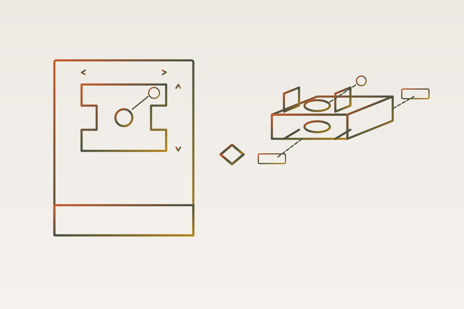
The underlying tension is simple to state. Model-Based Definition, or MBD, packs every piece of product and manufacturing information (GD&T, materials, surface finishes, tolerances) directly into the 3D CAD model as embedded data, usually called PMI. A 2D drawing carries that same intent a different way: as a separate, static document built to be read by a person. Neither format is wrong on its face. What matters is getting that intent to a given shop without it getting garbled along the way. This is a shop-readiness problem and a communication problem, not a matter of picking the more modern technology.
What a 2D drawing and an MBD model contain
Before weighing one format against the other, it helps to know what each one holds.
A 2D engineering drawing lays out geometry, dimensions, tolerances, material callouts, surface finish requirements, GD&T, notes, and assembly instructions on a flat, static page meant for a person to read.
MBD changes where that information lives. Instead of a separate document, the 3D CAD model itself becomes the single source of truth for geometry, dimensions, tolerances, materials, surface finishes, and every other annotation a shop needs. All of it together is called Product and Manufacturing Information, or PMI, embedded directly in the model.
What makes PMI different from a note on a drawing is that it's readable by machines, not just people. CAM software can pull toolpath data straight from it. Major CAD platforms, including PTC Creo, Siemens NX, CATIA, and SOLIDWORKS, support this kind of workflow, and all of them can export to neutral formats such as STEP AP242 or 3D PDF so the geometry and the annotations survive the trip to an outside shop.
There's a middle path between the two, and it matters more than it usually gets credit for. A Limited Dimension Drawing, or LDD, puts only the critical callouts on a 2D sheet and points the shop to the 3D model for everything else. Companies moving toward MBD often use this as a bridge: it lets them reference 3D geometry while still producing a drawing that fits into procurement systems and quality processes built around paper drawings. It's a deliberate transition tool, not a leftover habit.
Even with all the progress MBD has made, 2D drawings remain the primary carrier of manufacturing intent across a lot of industrial work, because a 3D model by itself often doesn't capture everything a shop needs to build a part correctly. GD&T constraints, datum references, surface finish requirements, and thread specifications still tend to live on a drawing, even in shops that work from 3D data for everything else.
2D Drawings for Custom Part Orders
For the bulk of custom part orders going to job shops and contract manufacturers, a well-prepared 2D drawing with complete GD&T is still the format that gets a part made correctly the first time. The reason comes down to reach: a drawing can be read by nearly anyone on a shop floor, while embedded PMI only benefits shops whose software on the other end can actually use it.
Entire industries are built around this. Automotive, aerospace, shipbuilding, and heavy-machinery supply chains still treat 2D drawings as the authoritative source for manufacturing semantics. The shop networks that serve those industries read drawings fluently, because generations of tooling, training, and quality systems were built around them.
For straightforward parts, a drawing does everything it needs to. A prismatic machined bracket, a turned shaft, a simple sheet metal bracket: give the shop clean views, a clear datum structure, and explicit tolerance callouts, and there's nothing left for a 3D PMI model to clear up. The part is simple enough that the drawing already communicates the full intent.
Drawings do have real limitations. But those costs stay low on a part ordered once, or in small volume, with a design that isn't changing. They only start to add up on long production runs that go through frequent engineering change orders, which is a different kind of job with a different set of risks. That's where the balance starts to shift.
The friction between what engineers assume shops can process and what shops actually accept is often the real bottleneck in fast-turn ordering.
Where 2D drawings break down
Drawings fail in predictable ways, and knowing those failure points is what lets an engineer catch them before they turn into a bad part.
Start with something as plain as a number on a sheet. A "10" next to a leader line could mean a hole diameter, a slot width, a fillet radius, or a depth, depending on drafting convention, where the leader points, and which view it's attached to. Get the interpretation wrong at that stage and the error doesn't stay contained. It carries through into manufacturing and then into inspection planning, where someone is now measuring the wrong feature against the wrong number.
Complex parts make this worse. A part with many interacting tolerances, compound angles, or features that don't translate cleanly into orthographic views forces whoever reads the drawing to interpret it, and different shops interpret the same drawing differently. That's how one RFQ comes back with three different quotes and three different sets of assumptions about what the part actually needs to be.
Version control is its own failure mode. In a drawing-centric workflow, GD&T annotations on the 2D sheet can drift out of sync with the 3D CAD model as the design goes through revisions, and that drift opens the door to version conflicts and misread tolerances. The risk climbs sharply on any part that goes through frequent engineering changes. The model moves on, the drawing stays behind, and a shop can end up building to a revision that's already obsolete.
Assemblies compound the problem further. That mental reconstruction is itself a source of error, and the more complex the assembly, the more room there is for something to get lost in translation.
When MBD improves the order
MBD earns its keep in three specific situations: complex parts, frequent design changes, and automated inspection workflows. Outside those situations, its advantages mostly go unused.
On the production side, MBD lets CAM software generate toolpaths and lets CMM measurement programs build inspection routines straight from the annotated 3D model. That cuts setup time and removes a step where someone would otherwise retype tolerance values by hand, which is exactly where human error tends to creep into data translation.
Design changes are where MBD shows its biggest advantage. Update the CAD model, and there's no separate 2D drawing to chase down and revise afterward. For a program running through frequent engineering change orders, that single difference can save real time on every revision cycle.
Geometry is the other clear case. A 3D model communicates those spatial relationships directly, where a drawing would need a pile of extra views and notes just to approximate the same information, and even then leave room for misreading.
None of that works without the right equipment on the receiving end. MBD only pays off if the shop has software that can read PMI out of a STEP AP242 file or a 3D PDF. Confirming that a shop can read PMI before sending an MBD-only package is the single most common reason MBD fails to deliver on a custom part order.
Even with automation improving, lining up drawing intent with 3D geometry is still a recognized challenge across industrial workflows, because drawing annotations depend on context and require interpretation. MBD reduces friction. It doesn't remove the need for judgment.
Fast-turn manufacturers like OneWeekParts close this gap by taking both drawing and model-based input and flagging manufacturability issues immediately, so engineers find out whether a file is readable and complete in seconds rather than waiting days for a shop to come back with questions.
How tolerance callouts and GD&T interact with format choice
Whatever format a file arrives in, the tolerance callout is the single element that decides whether a shop can quote the part accurately, build it correctly, and inspect it with confidence. Format changes how reliably that callout survives the trip from engineer to machinist.
On a 2D drawing, GD&T callouts are annotations meant for a person to read, tied to a specific view. Ambiguous callouts produce exactly the kind of variation described earlier: one quote assumes one tolerance, another shop assumes something slightly different, and the parts that come back don't match.
That risk scales with complexity. A part with many tight tolerances and an intricate datum structure gets more out of MBD's semantic GD&T than a simple part with a handful of plain plus-or-minus tolerances, because the odds of a callout getting misread rise as the callout structure gets more complicated.
Tolerance tightness needs to earn its place regardless of which format carries it. A precision tolerance on a chamfer or a cosmetic surface that doesn't need it forces the shop to switch to a slower process for no benefit to fit or function, which only adds cost. The better format for a given part is whichever one makes it easiest to check which tolerances are actually doing functional work and which ones are just habit.
Every tolerance tighter than standard should trace back to a specific functional requirement, in either format. If a drawing or a model can't answer why a particular callout is tight, that callout needs a second look before the file goes to the shop, not after the part comes back wrong.
What specialty processes need from the file you send
Format decisions get concrete fast once a specific manufacturing process enters the picture, because different processes need different minimum information to run correctly.
CNC machining takes 3D digital data straight into the machine to produce the final part. For simple prismatic and turned geometry, a clean STEP file paired with a drawing that covers critical tolerances and surface finishes is usually enough. Five-axis work with complex surface geometry is a different story: the model carries spatial information that a 2D drawing can't fully capture no matter how many views get added to the sheet.
Custom springs lean the other way. Most production spring projects still need an engineering drawing that spells out tolerances, materials, and inspection requirements. Regardless of which format shows up, final production still depends on confirmed dimensions, a specified material, and clear functional requirements.
Sheet metal fabrication has its own pressure points. A model with correctly applied sheet metal features makes those details easier to check up front, but a 2D drawing is still the standard delivery format for build-to-print sheet metal work at most job shops.
The same pattern explains all three cases. The more a process pulls data straight into a machine, such as a bending program reading LRA or XYZ coordinates, or a CAM system reading 3D geometry for five-axis toolpaths, the more a model contributes directly to the part getting made. The more a process depends on a person interpreting the file and setting up the job by hand, the more a drawing's clarity at the bench is what actually gets the part built right.
A practical decision framework for choosing format before you submit an order
Start with the part, not the format. A simple prismatic or turned part, ordered once or in modest volume, with a stable design, is well served by a clean 2D drawing carrying complete GD&T. There's nothing about that kind of part that embedded PMI would improve enough to justify the extra step of confirming a shop's software capability first.
Move toward MBD, or at least a hybrid LDD package, when the part has complex surface geometry, a dense set of interacting tolerances, or a datum structure that would take paragraphs of notes to explain on a flat sheet. Move toward it as well when the design is expected to go through several engineering changes after the first release, since that's where a drawing's manual update step becomes a real liability.
Before sending an MBD-only package anywhere, confirm the shop can actually read PMI out of a STEP AP242 file or a 3D PDF. A shop without that software gets a model it can print and look at, nothing more. That single check, made before the file goes out, prevents the exact kind of quoting delay and rework that started this whole discussion.
When a drawing has limitations, such as a version conflict, a missing GD&T callout, or a surface finish note that doesn't match the model, the cost compounds fast in rework and schedule slip. A single-vendor platform with same-day engineer support and upfront DFM feedback catches those problems during quoting, while they're still a quick clarification to resolve.
The format is a tool chosen to fit the part and the shop receiving it. Judge it against two questions: how much manufacturing intent does this part actually require to be built correctly, and can the shop on the other end read what's sent. Answer those honestly before the file goes out, and the quoting delays, ambiguous RFQs, and rework that prompted the question in the first place mostly don't happen.