Automated DFM Feedback in Instant Quoting Platforms
Instant manufacturability feedback catches design flaws before engineers move on.

The dominant failure in mechanical development has nothing to do with missing knowledge about how to manufacture a part well. Engineers generally know the rules. The failure is timing: that knowledge becomes available only after the design has already locked onto a direction, when changing course costs real money and real schedule.
Traditional DFM review happens at fixed checkpoints, a design review meeting, a supplier quote cycle, a formal DFMEA session, each one separated from the actual moment of design by days or weeks. An engineer finishes a feature, sends the file out, and waits. By the time a manufacturer sends back a list of flagged issues, the engineer has already moved on to the next assembly. The redesign has to restart from a schedule that already absorbed the delay before the fix even began. A 2024 CIMdata study estimated that late-stage design changes driven by manufacturability issues account for a significant share of total product development cost in discrete manufacturing. If you catch a design error late instead of during design review, it can cost an order of magnitude more to fix, sources say.
DFM knowledge is scattered: it lives in supplier guidelines, in tribal knowledge passed between manufacturing engineers, in the heads of people who have spent years watching what breaks on a shop floor, and that scattering is why the feedback arrives too late. None of that is reachable by a designer sitting in SolidWorks or CATIA mid-sketch. Worse, the rules themselves resist consolidation into one tidy reference, because they are process-specific, material-specific, and often specific to a given supplier's own equipment. A geometry that works cleanly in injection molding can be expensive or flat-out impossible in CNC machining. A sheet metal feature that bends without complaint can crack a glass-filled nylon part under the same load. Context decides everything, and no checklist captures all of it at once.
The fix is not another review meeting or a longer checklist. So the fix has to move the feedback signal upstream, to the moment of design itself, so manufacturability becomes visible while the file is still open instead of something an engineer learns about later.
How automated DFM feedback works when a file is uploaded
When a CAD file enters the system, automated DFM feedback starts right then, as a loop. Computational geometry algorithms scan the model, identify the features that matter, holes, pockets, thin walls, undercuts, and check them against manufacturing rules written for the specific process selected. All of this happens before a human estimator ever opens the file.
The analysis adapts to context instead of applying one blanket standard. The same wall thickness gets judged differently depending on whether the part is headed for CNC machining, injection molding, or sheet metal fabrication: a single fixed rule cannot serve every process, because the rules are process-specific, so the system has to know which process it is checking against before it can say anything useful. Flags appear as visual markers placed directly on the 3D model, so you see the exact feature causing trouble instead of a generic report to decode. The suggestions attached to those flags are specific too: a revised dimension, a tighter or looser tolerance, a different material, giving the engineer a path forward instead of a red warning triangle.
Tools built for this purpose fall into four rough categories as of 2026, each sitting at a different point in the design-to-manufacturing chain. Manual checklists are still the baseline, and engineers still have to remember to run through them. CAD-integrated plugins sit inside the design software itself, flagging common violations like thin walls and sharp corners as the model takes shape. Quoting-platform-embedded DFM is the category this article centers on: analysis runs the instant a file is uploaded into an instant quoting engine, tying manufacturability feedback directly to the price and lead time the engineer sees on screen. The newest category, AI-powered DFM and knowledge retrieval, drops the fixed rule library altogether in favor of models trained against industry standards, material datasheets, process guidelines, and a company's own manufacturing history.
That last shift matters because process-specific knowledge changes fast, and no static rule library can keep pace with it. An AI-trained engine can check a new design against an organization's own past engineering change orders, old supplier quality reports, and cost data pulled from prior production runs, information that never lived inside the CAD file to begin with. Most DFM tools fall short of this because the real value sits in organizational knowledge: hard-won manufacturing lessons that typically stay locked in a senior engineer's head or scattered across systems that do not talk to each other. Platforms built around this approach connect a design decision to the full history of how an organization has designed and built things before, making that history queryable the moment a file loads instead of something an engineer has to remember to ask about.
DFM Rules for CNC Machining and Sheet Metal
The content behind every DFM flag is a set of manufacturing constraints specific to a process, and understanding why those constraints exist separates an engineer who fixes the flagged feature from one who overrides it and waits for the quote to come back wrong.
CNC machining rules center on two things: how a tool physically reaches a feature, and how long that feature takes to cut. Internal radii should match standard end mill sizes, because when a radius forces a non-standard tool into the job, it adds cost and lead time you rarely see coming at the design stage. Deep pockets run up cycle time and chew through tooling faster, so if you reduce pocket depth or add a small draft angle, you can often cut cost the cheapest way. Unnecessary undercuts cause a disproportionate share of late-stage redesigns, because a feature that looks trivial in CAD can demand a multi-axis setup or a custom fixture, and that can double the machining cost. These failures do not appear as abstract warnings but as a quote that comes back incomplete or a lead time the project schedule cannot absorb.
Sheet metal fabrication runs on different physics entirely: it bends rather than cuts. Designing below the minimum bend radius for a given material and thickness causes cracking and distortion, a failure that frequently only becomes visible once the part is actually being formed, not during simulation. Formed features that stay simple hold tighter tolerances and move through the shop faster, but when complex forms look achievable in CAD, they often need secondary operations the shop prices as a separate line item. Tolerance expectations also shift based on where a feature sits relative to a bend: defaults tighten for features on a single flat surface and loosen substantially for features that span across multiple bends, a distinction most engineers do not carry in working memory while modeling. File preparation matters just as much as the design itself here. Parts need to be built using sheet metal-specific tools in the CAD platform, with bend lines, reliefs, and a proper flat pattern included, because a file that skips sheet-metal-aware modeling throws DFM flags the second it hits an automated quoting engine.
The through-line across both processes is the same: a feature that is correct for CNC machining is frequently wrong for sheet metal, and the reverse holds just as often. That is why one rule library can never cover a multi-process bill of materials, and it is why the move toward AI-trained, process-aware engines counts as a major upgrade. It is the necessary response to how complicated a modern BOM actually gets.
Embedding DFM in Quoting: The Economics of Error Discovery
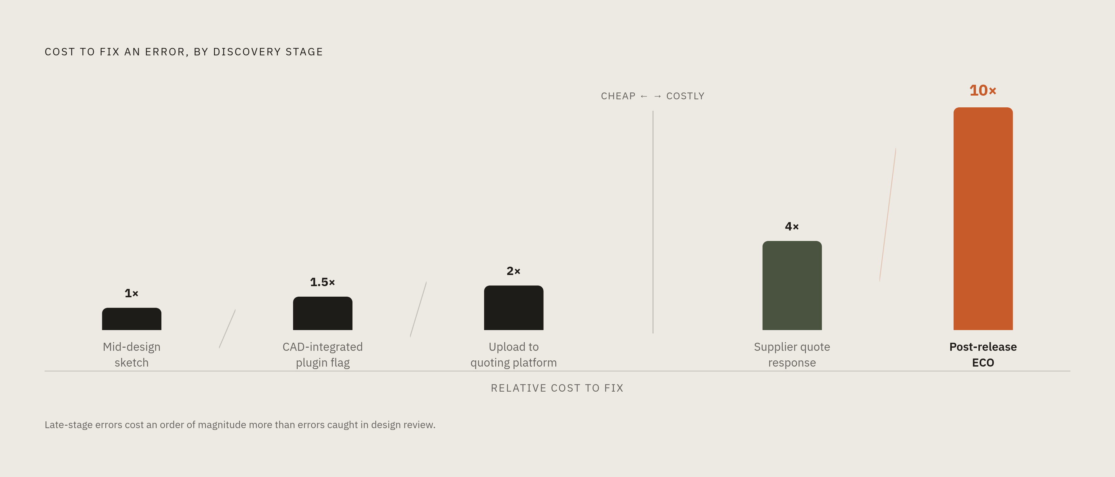
Moving DFM feedback into the quoting step rather than treating it as a downstream gate keeps the cost of finding an error low, because the flag arrives before an engineer has committed tooling, locked a schedule, or sent procurement after long-lead materials for a design that cannot be built as drawn.
The traditional model treats a supplier's quote response as the first real DFM signal. By the time that response lands, the design has already been released, reviewed, and often handed off to someone else entirely, so fixing it means opening an engineering change order, resetting the schedule, and frequently restarting the quote cycle from scratch. An upload-triggered DFM flag beats every one of those checkpoints: it appears before pricing is set, before tooling is committed, before procurement has sourced anything with a long lead time. Once you cross each of those boundaries, the identical fix costs more than it did the moment before. Instant quoting platforms that embed DFM analysis, OneWeekParts among them, surface manufacturability feedback the moment a CAD file is uploaded, so a gap that otherwise runs days or weeks collapses down to minutes in the quoting step itself, and the engineer still holds full context and can act on the flags cheaply.
The same logic carries further upstream, into early visibility into the manufacturing BOM. Engineers get feedback on part availability and cost while they are still designing, not after. Buyers can flag a long-lead-time component before it threatens a delivery date rather than after it already has. Manufacturing teams can weigh in on assembly constraints during early prototyping instead of waiting to find them at final inspection. None of that is possible when DFM review waits for a release gate that comes after the design is already frozen. A manufacturing BOM built and refined early in the development cycle, carrying supplier-specific components, cost roll-ups, lead times, and sourcing alternatives, turns from a record of past decisions into something that shapes the decisions still ahead.
Why a fragmented vendor model defeats instant DFM feedback on a full assembly
Instant DFM feedback on one part saves time. Instant DFM feedback across a complete mechanical BOM, spanning CNC machining, sheet metal, castings, and specialty fabrication, is what actually compresses a development cycle, and getting there requires a sourcing partner able to quote the entire assembly rather than cherry-picking the parts that are easy to handle.
A hardware team that sends CNC parts to one vendor, sheet metal to a second, and springs or gaskets to a third ends up with DFM feedback arriving in three separate loops, on three separate timelines, with nobody positioned to see how the parts actually fit together. Every handoff between vendors doubles as a handoff between DFM systems, or in some cases a handoff into a gap where no DFM system exists. The constraints that matter most at the assembly level, fit, clearance, how tolerances stack up across mating parts, fall straight into that gap. A multi-process platform like OneWeekParts can run process-specific DFM analysis across its full capability set, CNC, sheet metal, 3D printing, casting, carbon fiber, and more, inside a single upload, so an engineer gets manufacturability feedback across several process paths at once instead of chasing separate rule sets through separate vendors.
Consolidating sourcing under one partner is already a recognized way to improve supply chain performance and cut cost, but the DFM case for consolidation stands apart from the cost case. A partner who can see the whole BOM can flag assembly-level issues that no single-part vendor, working in isolation, would ever catch. The strongest objection deserves a direct answer: consolidating with one partner reduces flexibility and creates something closer to a single point of failure, and that concern is legitimate. But that risk is manageable with the right partner, while the risk of assembly-level DFM blindness from a fragmented vendor list is structural, and it gets worse with every additional vendor added to the mix. The real question during a prototype cycle is which risk is harder to recover from, and a missed tolerance stack-up discovered at final assembly tends to cost far more than the flexibility a second vendor might have offered.
DFM for specialty fabrication: springs, gaskets, and tube bending
Automated DFM feedback for standard CNC machining and sheet metal parts has matured into something reliable and fast. Specialty fabrication, custom springs, gaskets, and tube bending, is at an earlier point on that same maturity curve, where computational geometry sets the outer boundaries of what is possible and an experienced engineer still confirms the details that sit right at the edge.
Custom springs are at the hardest end of that spectrum. Tolerance and lead time only get confirmed after a full review of the drawing, the material, the quantity, and the inspection requirements, because geometry and production route interact in ways a fixed rule library cannot fully predict ahead of time. The stock-versus-custom spectrum shows why this is hard to automate cleanly. A supplier like MW Components carries roughly 40,000 stock spring designs ready for same-day shipping alongside fully custom manufacturing capability, and an instant quoting engine serious about springs has to navigate that entire range and quote custom designs as well as stock ones.
Custom gaskets need a drawing, a material callout, and an annual volume before they can be quoted with any accuracy. The DFM questions that matter here center on material compatibility, tooling cost, and tolerances that interact directly with the mating surface the gasket has to seal against. Tube bending sits as the most geometry-intensive of the three, where wall thickness, bend radius, and the sequence of bends along a single piece of tube all interact in ways that strain what a static rule set can check on its own.
None of this reflects a gap in the technology. It reflects where a serious sourcing partner draws the line between what computational geometry can check reliably and where a trained engineer still needs to put eyes on the file. Because manufacturing rules are process-specific and often tied to a particular supplier's own equipment, you need a single platform with broad process capability, not a marketplace routing files to whichever shop happens to be available, to ground DFM feedback in the actual processes and constraints that will build the part. That is the standard specialty fabrication gets held to, and it is the right one.
Sources
- DFM Analysis in 2026: The Best Tools for Getting Instant Manufacturing Feedback - Leo AI - Generative AI for Engineering CAD Design
- Best AI Tools for DFM: A Guide for Mechanical Engineers
- 50 DFM Tools, Software, And Techniques
- oneweekparts.com
- Instant quoting expands access to sheet metal and CNC tube bending
- CNC Design Guide: DFM Rules for Better Parts, Lower Cost, and Faster Quotes
- AI-Powered Instant Quoting Engine - Jawstec
- Top 10 Custom Spring Manufacturers in 2026