Revision Control Practices for Manufacturing Drawings in Prototype Programs
Encode program phase, not just change count, to keep prototype drawings legible.
Prototype programs run on speed, and formal revision control feels like the opposite of speed, so most engineering teams quietly drop it. The pace of design iteration makes a full release cycle feel like paperwork standing between the engineer and the next design pass, and the usual result is a drift toward date stamps and uncontrolled workaround drawings that nobody officially tracks. That drift does more than create messy folders. It makes drawings illegible: a vendor, a QC technician, or a new hire looking at an unmarked drawing has no way to tell whether it's a concept sketch, a build-ready document, or a revision that got superseded weeks ago. Most revision schemes were built to answer a production question, "which sequential change is this?" That question assumes a stable baseline and a slow cadence of controlled edits, a condition a prototype program doesn't have. What a prototype program needs is a scheme built to answer a different question: what was the intent when this drawing left the engineer's hands? A revision identifier that encodes program phase, not just change count, answers both questions at once, and that's the structural fix the rest of this piece works through.
Phase-Segmented Revision Schemes and Program State
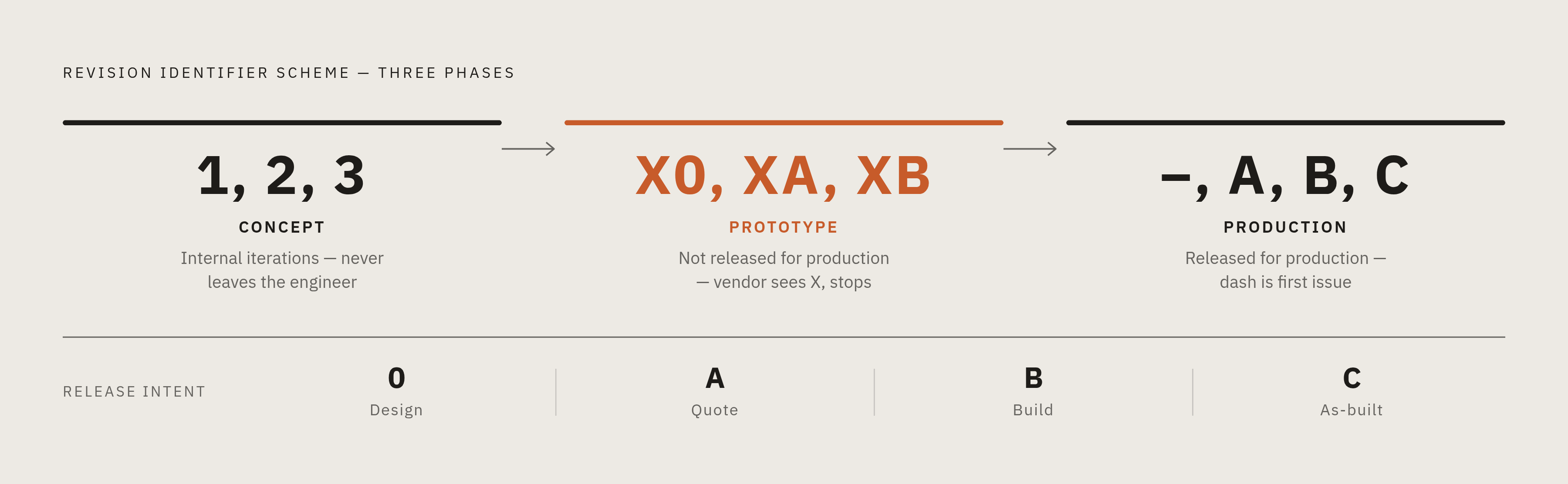
A phase-segmented scheme splits the revision namespace by program stage instead of running one continuous sequence from the first sketch to the production part. Done well, the revision identifier alone tells a reader what kind of document they're holding, with no supporting documentation required.
One widely used approach, discussed among practitioners on Eng-Tips around pre-production revision symbols, assigns a distinct format to each phase: concept drawings carry plain numerals (1, 2, 3), prototype drawings carry a prefix like "X0," "XA," or "XB," and production drawings begin at dash "–" and move through the standard alphabet, A, B, C, and onward. The X-prefix does real work here. A vendor who receives a drawing marked XB knows immediately that it's a prototype-phase document, not something released for production, without needing an email or a cover sheet to confirm it. The numeral-only concept phase serves a quieter purpose: it keeps early, fast-moving internal iterations visually and procedurally separate from anything that's about to leave the engineering team's hands.
A second, more rigorous approach encodes release intent directly into the letter itself rather than just the prefix. In this scheme, 0 means design, A means quote, B means build, and C means as-built, so the revision letter tells a reader what the drawing was released for, not merely how many times someone touched it. That precision comes at a cost: it demands strict stage-gating discipline, and it creates an audit burden that can be heavier than a fast-moving early-phase program wants to carry.
Both schemes rest on the same principle. A revision identifier has to mean something to someone who wasn't in the design review, and it has to still mean something years later when a field failure forces a team to reconstruct what was built and when. One practical note belongs here regardless of which scheme a team picks: avoid the letters I, L, and O in any alphanumeric sequence, since they're easily mistaken for the numerals 1, 1, and 0 on a faded print or under bad shop lighting, a small rule with real consequences at receiving inspection. And within any phase, minor changes don't need to force a jump to the next major letter. Decimal notation, A.1, A.2, lets a team track sub-iterations while keeping the major revision boundary meaningful.
When a revision must be incremented and what the revision block must say
The question engineers get wrong most often isn't about format, it's about timing: when does a drawing actually need a new revision? The real trigger is the drawing leaving the engineer's direct control, and that distinction is what separates real traceability from the appearance of it. The framework laid out by Industrial Monitor Direct maps this clearly. Internal iterations that never leave the engineer's own workstation don't need an increment. The moment a drawing is posted to a company intranet for design review, sent to a supplier for quotation, shared with a customer, copied to purchasing or QC, or transmitted electronically by any means, it needs one. Hard copy prints need an increment too, and every physical copy in circulation has to be tracked. When a drawing goes out to a vendor, a requisition listing the document number and revision has to accompany it, and if that drawing changes afterward, the vendor needs explicit notice so they can review their quote and adjust their fabrication process before any material gets cut.
The revision block description is where this discipline either holds up or quietly falls apart. A description that reads "Updated per ECO-1042" only works as long as that ECO document stays accessible. The moment it's lost, reorganized, or simply unreachable by someone new to the team, the revision history turns opaque. Compare that to a description that reads "Updated per ECO-1042: changed hole pattern on flange face from 4×M6 to 6×M8 per customer RFI-217." That version stays informative years later, with no reference documents needed, because the change describes itself. One more rule matters here, and it's short: superseded revisions never get deleted. Products already in service were built from them, and a field failure investigation depends on knowing precisely which design was current at the time of manufacture.
Why shared drives cannot sustain phase-aware revision control as prototype programs scale
Shared drives, email threads, and file-naming conventions work fine as survival tactics for a small team moving fast, but they aren't version control systems, and they fail in predictable ways as the number of files, contributors, and outside handoffs grows. Autodesk's analysis of version confusion in manufacturing traces how this breaks down: engineers save models to local folders "just for now," drawings get copied into multiple project directories, STEP files and PDFs get emailed straight to suppliers, and files get renamed as a makeshift revision system. Once several versions of the same design are circulating that way, the idea of a single source of truth disappears. The fallout isn't just a messy folder structure. Parts get machined to superseded drawings, assemblies don't fit, scrap and rework pile up, and the cause often gets blamed on shop error when the real problem was uncontrolled data.
A PDM system exists to solve exactly this structural gap. It manages revisions, controls who can access and edit what, preserves the relationships between models and drawings, and builds the traceability that the trigger rules from the previous section require but can't enforce on their own. At the more comprehensive end of the spectrum, PLM platforms including Siemens Teamcenter, PTC Windchill, and Dassault Enovia add cross-program BOM management, change-order workflows, and audit trails built for programs carrying regulatory or certification requirements.
A prototype program doesn't need the full weight of a PLM platform to get this right. The minimum viable system enforces check-in and check-out, auto-increments revision numbers on release, and preserves the full revision history without allowing anything to be overwritten, the PDM floor rather than the PLM ceiling. The common objection, that setting up a PDM system slows down the fast iteration prototype programs depend on, gets answered by the check-in/check-out model itself: engineers keep working freely in local CAD sessions and only commit to the managed vault at the trigger events already defined. The speed of iteration stays the same. Only the moment of release gets formalized.
What a Manufacturing Partner Needs to Build by Revision Phase
A drawing's revision phase tells a manufacturing partner what kind of commitment they're being asked to make. A vendor who can't read that signal off the drawing itself will either over-build their process for what's really just a concept test, or under-prepare for a prototype that's meant to behave like production hardware.
At the build phase, process-specific design-for-manufacturing requirements become binding in ways that directly affect cost and schedule. For machined parts, specifying tolerances tighter than what the part functionally needs drives up cycle time and inspection cost without adding value. For sheet metal, tight tolerances should apply only to assembly-critical features, with a general-tolerance standard covering everything else. For tube bending, material elongation above a certain threshold allows complex bends without annealing, and aerospace-grade tube work carries its own specific angular and positional accuracy requirements. None of that can be priced or planned correctly if the vendor doesn't know whether the drawing in front of them represents a quote-stage concept or a build-stage commitment.
The as-built revision is a distinct document event that records the actual condition of the fabricated hardware, including any field deviations accepted during the build, and it becomes the baseline for any change order that follows. In rigorous programs, every change order requires a new production package, tested, proven, and documented with a first article, before the previous process gets archived, and the as-built drawing is the anchor that whole chain hangs on.
Specialty processes make the stakes concrete. A spring manufacturer working from client-provided drawings starts production only after first-article prototypes are approved. The drawing presented at first article has to be the exact revision that will later govern full production. A gasket manufacturer running several fabrication processes under one roof, die cutting, flash cutting, lathe cutting, slitting, and machining, applies incoming material verification, in-process inspection, and lot traceability against a specific drawing revision, and any ambiguity about which revision governs a given lot breaks that chain. They're the exact failure points where an unmarked or ambiguous revision turns into a quality dispute.
How early, phase-tagged drawing releases reduce the cost of late-stage changes
DFM problems caught late cost far more to fix than the same problems caught during the concept or quote phase, and a phase-aware revision scheme creates the checkpoints where a manufacturing partner can flag those problems before tooling, fixtures, or material get committed. The single highest-leverage moment in a prototype program is the DFM review tied to the quote-phase drawing release. That's when a capable manufacturing partner can catch collision issues, undercut geometries, springback in tube bends, and tolerance conflicts that otherwise appear mid-build as scrap or rework. For tube fabrication programs specifically, running DFM reviews at the prototype-drawing stage catches collision, springback, and flange interference while they're still cheap to fix on paper, long before they turn expensive in tooling.
That same discipline applies at the BOM level. A prototype BOM that flags long-lead items, single-source dependencies, and components that aren't production-representative, submitted at the prototype drawing release, gives the production team options that simply vanish if those same issues appear later, at the transition to volume manufacturing. Submitting a complete, accurate BOM alongside the drawing package, instead of sending it separately and later, lets the manufacturing partner flag supply-chain risk before it turns into a build blocker.
There's a coordination benefit here too. Consolidating the full mechanical BOM, across CNC machined parts, sheet metal, specialty fabrication, and assemblies, with a single manufacturing partner that can quote and inspect every process against one shared revision record removes the coordination overhead and quality-dispute risk that comes with splitting the work across a fragmented vendor list. A partner capable of handling the full spread of processes, CNC milling and turning, sheet metal, 3D printing, carbon fiber, urethane casting, custom springs, gaskets, tube bending, wire EDM, and more, under one quote and one purchase order, can apply DFM feedback at the point of quoting, before a single part gets cut, and can inspect every part against that same revision before it ships.
Phase-aware revision control was never really about compliance; the actual goal is speed with traceability intact. A prototype program that releases drawings at defined phase gates, with self-describing revision blocks and a PDM-enforced single source of truth, moves faster than one running on date stamps and workaround files, because it cuts out the rework, the vendor miscommunication, and the field-failure investigations that uncontrolled drawings create down the line.
Sources
- Drawing Revision Control Best Practices for Engineering
- Pre-Production Drawing Revision Symbols
- Version Control in Manufacturing: Stop Designing on Outdated Data Before It Costs You Profit - Design & Manufacturing
- Drawing Revision Numbering: 6 Letters to Skip, Rev 0 vs 1
- PDM Workflow: Revision Control, Approvals & Release
- Managing Engineering Changes (ECOs) with Your Contract Manufacturer
- Version Control for Engineering Drawings