STEP vs IGES vs Native CAD Files for Manufacturing Quotes
Choosing the right file format can cut days from your manufacturing quote.
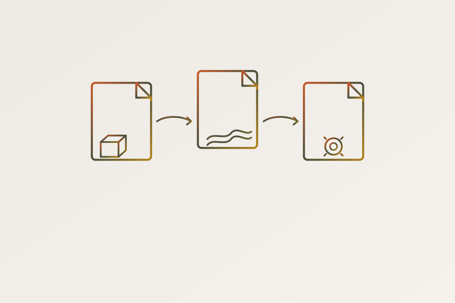
A design file is an instruction set, and the format it's saved in determines how much of that instruction set actually survives the trip to a manufacturer. Send the wrong one, and the consequence isn't abstract: a quote gets delayed, a shop requotes the job, or worse, what comes back doesn't match what was designed. Every engineer who has sent a CAD export off to a supplier has hit some version of this, usually right before a deadline, usually without knowing which format choice caused it.
How file format changes what a manufacturer can do with a design
A manufacturer can only quote and build what the file tells them. A mesh file shows shape but strips away design intent. A neutral solid carries geometry but not the parametric history behind it. A 2D drawing can define dimensions precisely, but it gives no machinable 3D geometry on its own. None of these gaps are cosmetic. They determine whether a shop can generate accurate toolpaths on the first pass or has to stop and ask questions, and every round of back-and-forth adds days to a quote that should have taken hours.
The reason formats diverge this much comes down to how each one represents geometry. Solid formats store exact mathematical surfaces. Mesh formats approximate those same surfaces as a field of triangles. 2D formats don't carry solid geometry at all, just lines and dimensions on a flat plane. A solid format using boundary representation, B-rep, describes a part with true mathematical surfaces, edges, and curves, so a cylinder is stored as an actual cylinder. Mesh formats like STL and OBJ describe that same surface as thousands of small flat triangles. That approximation works fine for additive manufacturing, where the printer is laying down discrete layers anyway and some faceting is inherent to the process. CNC toolpath generation needs exact geometry to cut clean surfaces, so if you feed a mesh into a CAM system, you tend to get lower-quality, less precise toolpaths than if you feed it a true solid.
Solid versus mesh is a single distinction, but it explains why the same file can be exactly right for one process and wrong for another. A part destined for a 3D printer can travel as an STL with no real loss. The same part destined for a CNC mill needs a solid format, or the shop is machining against an approximation instead of the actual design. This is also why platforms handling complex multi-process assemblies, such as OneWeekParts, depend on receiving geometry in a format that preserves exact solid data, assembly structure, and tolerance information without loss: when that data arrives intact, quoting and toolpath generation happen on the first pass instead of after a round of file corrections.
STEP and its role as the manufacturing exchange default
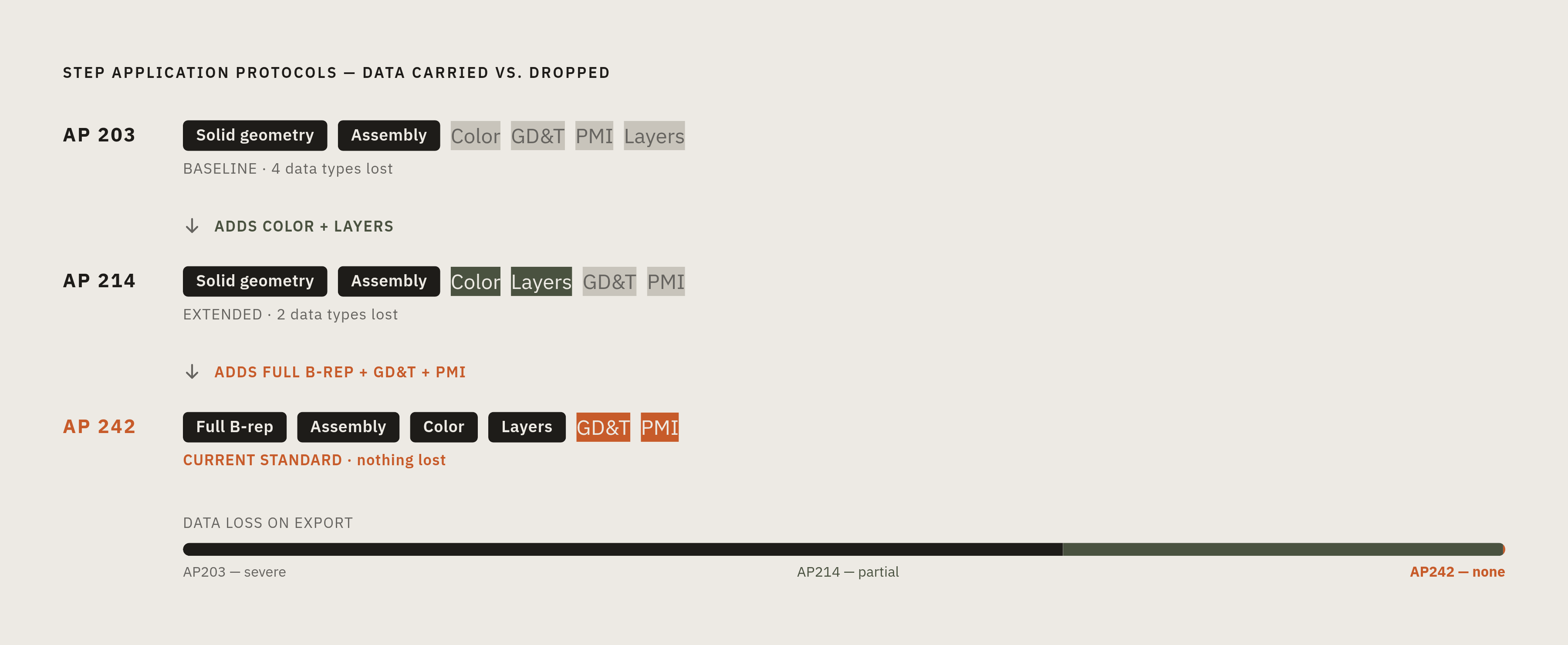
STEP has become the manufacturing industry's default exchange format because it carries exact B-rep geometry, full assembly structure, and, in its newer revisions, the tolerance and PMI data that quoting and inspection actually depend on. STEP, formally ISO 10303, stores full solid geometry, assembly structure, colors, layers, and, in its newest application protocol, product manufacturing information such as GD&T and tolerance callouts. Nearly every major CAD system on the market can export clean STEP, so it became the common language between them.
That interoperability is the practical payoff. A STEP file built in SolidWorks can be imported into Fusion 360, Creo, NX, or a machine shop's CAM software and will typically keep its solid B-rep geometry intact, though complex surfaces or tolerance mismatches can occasionally introduce geometry issues on import. There's no requirement that the receiving shop own the same software the file was created in. Because the geometry is exact and watertight, CNC toolpath generation can work directly from it, and the machinist ends up cutting from the same mathematical surfaces the engineer originally modeled, not a reconstruction of them.
STEP isn't one monolithic format, though, so the application protocol you choose on export determines which data survives the trip to the recipient. AP203 covers configuration-controlled 3D design, so you can treat it as the baseline solid and assembly format. AP214 builds on that by adding color and layer data, and automotive workflows use it heavily. AP242 is the current standard, merging both earlier protocols and adding full GD&T annotations and PMI. These three are not interchangeable, and exporting the wrong one can silently drop information the recipient needed. If color or GD&T data matters downstream, skip AP203, because those fields just vanish from the file with no warning. For most manufacturing quote packages, AP242 is the right export, with AP214 as a reasonable fallback where AP242 support isn't available. AP203 remains acceptable only when the accompanying drawing carries all tolerance and finish information separately, so nothing is lost by the model's omission. Because AP214 and AP242 carry that GD&T and PMI data alongside full B-rep geometry and assembly structure, a manufacturer can quote CNC machining, sheet metal, 3D printing, casting, and custom sub-assemblies from a single clean file, without format translation between processes, which is part of why single-vendor sourcing of a full mechanical BOM depends on getting the application protocol right. When in doubt, export AP242.
What IGES is, why it still exists, and the cases where it remains the right choice
IGES earns its place as a legacy format, and it fills a narrow but genuine role for older CAM seats and workflows that can't reliably read STEP. IGES stores geometry as individual surfaces, curves, and wireframe entities. There's no formal assembly tree, no native PMI, and the standard itself has been frozen at version 5.3 since 1996, so it hasn't evolved alongside modern CAD the way STEP has.
That surface-by-surface structure has a direct, practical cost on import. Because IGES describes each surface independently instead of as a unified solid, an imported IGES model often arrives as a loose collection of faces with tiny gaps at the seams. Those gaps need to be "healed" or stitched together before the geometry is usable for machining, and errors creep in during that stitching step. IGES is more prone to gaps and junk geometry on import than STEP. Experienced shops ask for STEP first and reach for IGES only when nothing else is on offer. For quoting, inspection, assembly review, or extracting weight and BOM data, STEP wins on every measure that matters.
Converting an IGES file to STEP doesn't fix any of this, because a converter can only translate what's already in the file. If the IGES arrived as loose, ungapped surfaces, running it through a converter just gives you loose surfaces wrapped in a newer file extension, not a healed solid. When you can, go back to whoever owns the native CAD model and ask for a direct STEP export in AP214 or AP242. A native re-export preserves solids, assembly structure, and color data in a way that file-to-file conversion simply cannot reconstruct. A round trip through IGES can't recover what IGES never stored in the first place: assemblies, solid topology, and PMI are lost the moment the file is exported as IGES, and converting back to STEP afterward doesn't bring any of it back. None of this makes IGES a bad format for the job it was built for. Engineers working against a legacy CAM seat or pulling geometry from an old archive are operating under real constraints, and IGES remains the correct tool in those specific cases.
Where native CAD files fit for sharing parametric source files
Native CAD files carry more information than any neutral format: they hold the full design history, not just the finished geometry. But that completeness comes with a dependency that makes native files a poor default for manufacturing exchange. A.sldprt from SolidWorks, a.f3d from Fusion 360, an.ipt from Inventor, each holds the complete design including feature history and parametric relationships between features. These files generally only open in their original software or a compatible version of it, so a manufacturer receiving a native file needs that same software at a matching or compatible version, and for most shops that's not something to count on, which is a large part of why STEP remains the better default for most handoffs.
There are two situations where sending native files genuinely makes sense. The first is when a manufacturer needs to modify geometry directly, rather than flag a fillet radius, a draft angle, or a wall thickness as a DFM issue and wait for a revised export to come back. Direct access to the feature tree lets that adjustment happen in minutes. The second is when a design partner is working inside the same CAD ecosystem, such as a contract engineering firm operating on the same SolidWorks seat. In that case, full parametric access speeds up collaboration, but if you share STEP instead, it strips out the feature tree that partner actually needs to work efficiently.
Outside those two cases, native files aren't the right default for sending work to a manufacturer. For most quote packages, the right combination is STEP for geometry, a PDF drawing for specification, and process-specific formats layered in wherever a given process calls for a different kind of input.
What a complete quote package contains
A 3D model on its own cannot be quoted accurately, no matter how clean the geometry is, because it says nothing about material, tolerances, finish, or secondary operations, and all of those drive price and lead time just as much as the shape does. A complete RFQ package needs a clean STEP model, a PDF drawing where tolerances and GD&T apply, a fully defined material specification, quantity, finish requirements, and clearly flagged critical-to-quality features or inspection notes. That material specification has to go beyond "aluminum" or "stainless": the alloy, temper, and governing standard, whether ASTM, AMS, or MIL, all need to be called out, because they affect machinability, material cost, and how long stock procurement takes. Consider a machined housing. The machinist can generate toolpaths straight from the STEP geometry, but the drawing still has to define datums, tolerances, thread callouts, surface finish, and inspection requirements, none of which the STEP file carries on its own.
One of the most expensive mistakes in an RFQ package has nothing to do with which format was chosen. If a 3D model and a 2D drawing are built to different revisions, you'll quote two different parts, and nobody notices until the mismatch appears in production, sometimes only after it has already started. That's a process discipline failure, not a format failure, and no amount of STEP sophistication fixes it. Keeping the model and drawing locked to the same revision at submission time matters as much as picking the right file type.
Process-specific formats fill in where the fabrication method works from a different kind of input than a 3D solid. Laser cutting, waterjet, and CNC punching all run from DXF flat profiles, and sending only a 3D STEP to a 2D cutting operation forces the operator to derive that flat profile by hand, which introduces both error and delay. Including the DXF alongside noted material thickness avoids that step. For sheet metal parts that get formed after cutting, the package needs both the DXF flat pattern and a STEP of the folded part, so the fabricator can check the formed geometry and the bend sequence against each other before cutting anything. This is the kind of package that separates a platform quoting a full mechanical BOM, castings, sheet metal, 3D printing, custom sub-assemblies, and the parts other shops decline to touch, from one that only takes on the easy geometry. OneWeekParts builds itself around that full package instead of a cherry-picked subset of it, so you get a single quote covering an entire BOM instead of a dozen separate submissions to a dozen separate vendors.
How DFM interacts with the file you send
Sending a flawless STEP file of a part that has DFM problems baked into its geometry doesn't prevent a quoting delay. It just delivers that same problem faster and in sharper detail. A part that's geometrically non-compliant will still fail DFM review no matter how clean the file format is, because the format only controls how accurately the geometry gets communicated, not whether that geometry can actually be machined or formed efficiently. If you catch DFM feedback during quoting, it costs far less than feedback that surfaces after the quote has already gone out, and far less still than feedback that arrives after production has started.
On the CNC machining side, the issues that come up most often at quote review are internal corner radii too tight for the available tooling, pocket depth-to-width ratios that exceed what standard tooling can reach, and features that demand more machine setups than the geometry justifies. Pocket depth should stay within roughly a 4:1 ratio against pocket width so standard tooling can reach it cleanly, but if you go deeper than that, the job needs special tooling or EDM, and both add cost and stretch the lead time. Features that can only be reached from more than two setups multiply fixturing cost accordingly, so designing a part for two-setup access keeps the machining side of the job lean.
Sheet metal carries its own set of DFM issues, and most of them are visible in the CAD model well before the file ever gets sent out. Hole-to-bend clearance violations, flange heights too short for a press brake to grip properly, and missing bend relief cuts at intersecting bends all fall into this category, and all of them are catchable at the modeling stage. Building sheet metal parts with the CAD platform's actual sheet metal tools, instead of modeling them as generic solids, makes sure the geometry carries proper bend lines, relief cuts, and a flat pattern the fabricator can use directly, and it exports a DXF flat pattern that matches the 3D model. Getting the file format right gets the geometry to the shop intact.