Functional Prototype Testing With 3D Printed vs Machined Parts
Printed parts validate geometry fast, but machined prototypes prove production performance.
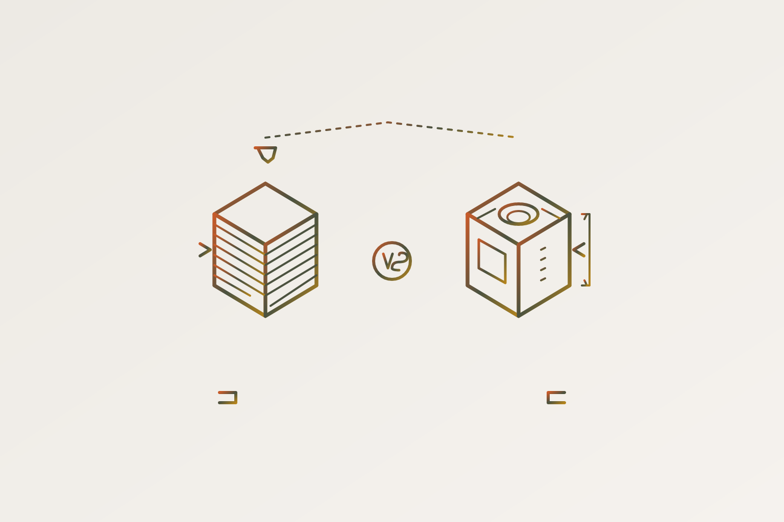
Functional prototype testing with 3D printed vs machined parts comes down to which process can produce data the test can trust. For hardware startups seeking fast-turn custom parts, printing suits early geometry checks, while machining suits tests that need production-equivalent material, precision fits, or controlled surfaces. A mixed assembly may need both, with each process assigned to what the next development decision needs to prove.
Why the process-versus-speed framing leads engineers to bad test data
The prototype arrives, and the problems start with the bore stack, bracket deflection, or a binding slide. Those problems expose the gap between a design on screen and its physical behavior. But finding a failure is not the same as understanding it. If the prototype’s material or manufacturing method differs from what the test requires, the result may say more about the surrogate than the design.
That is why “print it fast or machine it right” is the wrong framing. A functional prototype is a data instrument. It must match production-intent geometry, material behavior, and assembly interfaces closely enough for the test at hand. Speed and cost matter only after that requirement is clear, because a quick result that cannot support a decision is not useful progress.
What functional tests are actually asking of a prototype
A mechanical requirements brief gives the process decision a basis. It should state expected loads, operating temperature range, required tolerances, and assembly interfaces. Mechanical strength tests whether the part can carry its load, while dimensional accuracy tests whether its critical features have the specified dimensions. Assembly fit and movement test how parts work together, sealing tests the fluid interface, and thermal resistance and fatigue test how the part behaves under heat and repeated loading. A drop-impact housing and a fluid-flow fixture therefore need different kinds of fidelity.
Design verification asks whether the part was designed correctly, while functional testing asks whether it works as intended in real use. Manufacturability assessment asks whether it can be made efficiently and repeatedly, which requires a process close enough to production to expose tooling and fixturing constraints. Regulatory and compliance testing, where applicable, typically demands production-equivalent material. This mapping discipline also informs platforms such as OneWeekParts, where the manufacturing process is matched to the validation requirement.
Where 3D printing produces trustworthy functional data and where it does not
Layer orientation is the first mechanical issue to settle for a printed prototype. An FDM part loaded perpendicular to its layer lines can fail at a fraction of the load it could carry with layers parallel to the stress. The same geometry can therefore produce very different results depending on how it was printed. Orientation must be set in the test specification as well as in the shop. SLS produces isotropic parts without support structures, making it a stronger candidate when the load direction is not fully controlled.
Within those limits, printing can provide useful evidence about clearances, snap-fit geometry, assembly sequencing, and fluid-flow fixtures. FDM suits low-cost structural iteration in engineering thermoplastics, while SLA suits detailed geometry and fluid interfaces needing tighter dimensional accuracy. DMLS/SLM can print parts in metal, but metal alone does not make a printed part suitable for a given test. The chosen process still has to meet the relevant material, dimensional, and surface requirements.
Strong engineering resins and nylon do not erase that boundary. A printed surrogate cannot establish production durability, fatigue, wear against mating metal parts, or thermal resistance when it does not replicate the required material behavior. Infill and finishing also affect repeatability, so rectilinear or gyroid infill is preferable to grid where node stress concentration matters. Supports should avoid functional surfaces where possible, and cleaning, curing, and inspection cannot be skipped without weakening confidence in the result.
Where CNC machining produces trustworthy functional data and where its cost creates risk
CNC machining earns its place when the test depends on production-equivalent stock, precision, or surface finish. Materials including ABS, PC, POM, aluminum, and stainless steel let a prototype represent the behavior needed for strength, heat, and wear testing. CNC can consistently achieve tolerances of ±0.05 mm or better, with precision features as tight as ±0.01 mm. That capability matters for bearing interfaces, seal geometry, and mating surfaces where a dimensional error would change the test itself.
Blackrock Engineering’s gripper case shows the risk of buying that fidelity too soon. The team chose CNC machining in production materials before validating the geometry. A fundamental flaw appeared during first assembly, leaving the prototype as scrap and consuming the budget before a corrected design could be machined. Expensive parts answered a question that a cheaper geometry check should have settled first.
Machining also needs physical tool access, so deep pockets, sharp internal corners, undercuts, and internal cavities deserve DFM review before an order. Internal radii matched to standard end mill sizes, shallower pockets, and fewer unnecessary undercuts reduce machining burden. Those changes must keep the features the test is meant to check. CNC may be necessary for credible final evidence, yet spending on it before the design is ready can exhaust the testing program.
How the test stage — not the part geometry — should determine which process is used
A stage-gate sequence resolves that tension by making each build earn the next one. At concept validation, FDM or SLA can check shape and basic geometry before the build needs production material. During functional development, engineering-grade printed parts may work for specific tests if their properties and tolerances meet the requirements. Engineering prototypes and late-stage DVT builds favor CNC in production-equivalent material when the evidence must support design validation before tooling or a production release decision. Pre-production samples then need to confirm quality with basic geometry questions already settled.
The required proof defines the gate. Printing may suit a functional build that tests clearances, while a build at the same stage that tests wear may need machining. Even a complex shape may be a poor fit for additive manufacturing when the critical test needs the material behavior of a machined part. Geometry constrains how a part can be made, but the validation objective determines which available process is acceptable.
Early printing is valuable because it permits multiple design cycles in the time one CNC prototype may require. That speed has a purpose, namely stabilizing the design before paying for higher-fidelity evidence. Once the objective is design verification, functional testing, manufacturability assessment, or compliance, the process follows from its requirements. The calendar then becomes a delivery constraint.
How material choice determines whether test data transfers to a production release decision
Production-equivalent material means more than a familiar name on an order. A prototype with different mechanical properties may fit perfectly and still provide no basis for a strength, heat-resistance, or wear decision. Those tests need actual production-grade material, and CNC is often the right or only way to get it among the options under review. Supplier capability remains a separate constraint. JLCCNC, for example, does not offer titanium or PEEK CNC machining, even though those materials may be required by a production specification.
Carbon fiber makes the distinction especially clear. A CNC-machined prototype made from a uniform laminate does not necessarily reproduce a production layup whose fibers follow the part’s load paths. The mismatch matters particularly for complex curves and highly directional loads. Hand layup comes closest to matching the mechanical properties of the final production part, but takes longer and costs more per part.
In early composite development, aluminum alloys or nylon can be used to test geometry before the team commits to carbon fiber stock that costs more and is hard to machine. That substitution can settle the shape, but it cannot show how the final composite will behave mechanically. Material fidelity should rise when the decision needs it.
When a hybrid build — printed structure, machined critical features — produces better data than either process alone
Blackrock Engineering’s gripper case also illustrates how to divide a build by function. The hybrid option assigned the complex base plate and brackets to 3D printing, the load-bearing jaw mechanism and mounting pins to machining, and the pneumatic elements to off-the-shelf components. That division supported fit-and-function validation at a fraction of the all-machined cost and time. The fully printed option showed that the redesign worked, but could not give load-bearing data the team could trust. The hybrid approach preserved mechanical fidelity where the validation needed it.
Internal channels, organic shapes, and lightweight lattices favor printing when their role is geometric. Precision flats, deep threaded holes, seal surfaces, and wear interfaces are better suited to machining when how they work depends on their dimensions or how their surfaces behave. A printed structure is therefore appropriate only when its own behavior does not undermine the intended mechanical test.
Hybrid work can also happen within a part or manufacturing sequence. Metal printing can supply the near-net shape, followed by machining of surfaces that need tighter tolerances or a better finish. Printed tooling and fixtures can shorten preparation for CNC work without changing the machined prototype’s required material or dimensions. The benefit is not simply splitting the bill. It comes from stating exactly what each process must contribute to valid evidence.
How consolidating a multi-process BOM with one supplier changes what prototype testing can prove
That component-level discipline has to survive sourcing. An assembly test cannot begin until its machined parts, printed brackets, sheet metal, springs, gaskets, and tube-bent fittings are all available. A single late component holds the test, while a substitute with the wrong material or tolerance can change what the result means. Using several vendors for the build also adds variation that no single part’s inspection report can fully show. How the assembly behaves depends on the interfaces between parts, even when each shipment passes inspection.
Using one supplier helps coordinate the build, but the team still needs a sound test specification. OneWeekParts offers CNC machining, 3D printing, sheet metal fabrication, and other custom components through one quote, one purchase order, and one shipment. Its same-day engineer support and quoting-stage DFM feedback provide a way to resolve process and material choices before manufacturing. That makes it one sourcing option for a mixed-process functional build, rather than a reason to force every component through the same method. Casting or sheet metal can remain part of the build where production intent requires them.
There is also a design route to fewer incoming parts. Additive manufacturing can integrate alignment and fastening features into component geometry, reducing the items to inspect and coordinate. When the build still needs separate components, using one supplier can help bring them together as specified.
A working decision guide for matching process to test type
Before selecting a process, write what the test must prove as geometry and fit, mechanical performance, material durability, assembly behavior, or regulatory compliance. Second, process selection depends on whether the answer must transfer to production-material behavior. If it must, use CNC in the required production material where machining can provide the needed fidelity, while treating composite layup as a separate qualification. If it need not, printing may be adequate with a process and orientation matched to the test.
Third, machining requires geometry stable enough to justify it. If substantial redesign is still likely, use printed parts to settle geometry first. Fourth, process selection must account for whether the assembly contains mixed validation requirements. If it does, assign printing to suitable geometry checks and machining to mechanically critical interfaces, then consider whether one source can deliver the complete build. For teams assessing OneWeekParts or separate specialist shops, the sourcing test is whether the required mix can arrive quickly without sacrificing material properties or dimensional accuracy.
Finally, apply strict tolerances only to functional features, including fits, alignments, seals, bearings, and critical interfaces. Record the material lot, tolerance callouts, print orientation, infill, post-processing, surface finish, and fixturing relevant to each iteration. Those records make a successful result reproducible and a failure diagnosable. A good prototype is the one whose data is credible enough to support the next decision.