Specifying Surface Roughness on Machined Part Drawings
Different roughness parameters catch different failure modes in service.
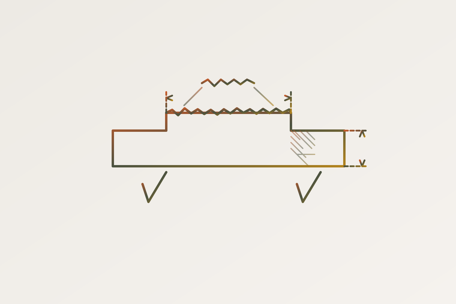
A roughness callout on a machined part drawing is a functional spec, on par with a bore diameter or a thread pitch, and getting it wrong sends parts back, burns machine time, or puts a seal into service that was never going to hold.
Why surface roughness belongs on every machined part drawing
Surface roughness describes the microscopic peaks and valleys a cutting tool leaves behind, and those peaks and valleys decide how a part behaves once it's installed. Friction, wear, sealing, coating adhesion, fatigue life: all of it traces back to that texture. A dimensional tolerance tells a machinist how big to make a feature. A roughness callout tells them what that feature's surface has to do once the part is in service, and both are equally capable of making or breaking a design.
Two mistakes show up constantly in practice, and both cost real money. Over-specification asks for a finer finish than the part actually needs, which adds machining time and often a secondary operation for no functional payoff. Under-specification does the opposite: it leaves a sealing or bearing surface rough enough that it wears out early or leaks. Picture a static O-ring face machined to a standard as-milled finish instead of the smoother texture a seal needs to seat against. The seal never makes full contact, and the leak doesn't appear on the bench. It becomes visible in the field, after the part has shipped. Every decision covered in this piece, from parameter choice to symbol placement to unit conventions, exists to keep that failure from happening.
When to use Ra, Rz, or Rq
Before a number goes on a drawing, the engineer has to decide which number. Ra, Rz, and Rq each measure roughness differently, and picking the wrong one can let a bad surface pass inspection while looking fine on paper.
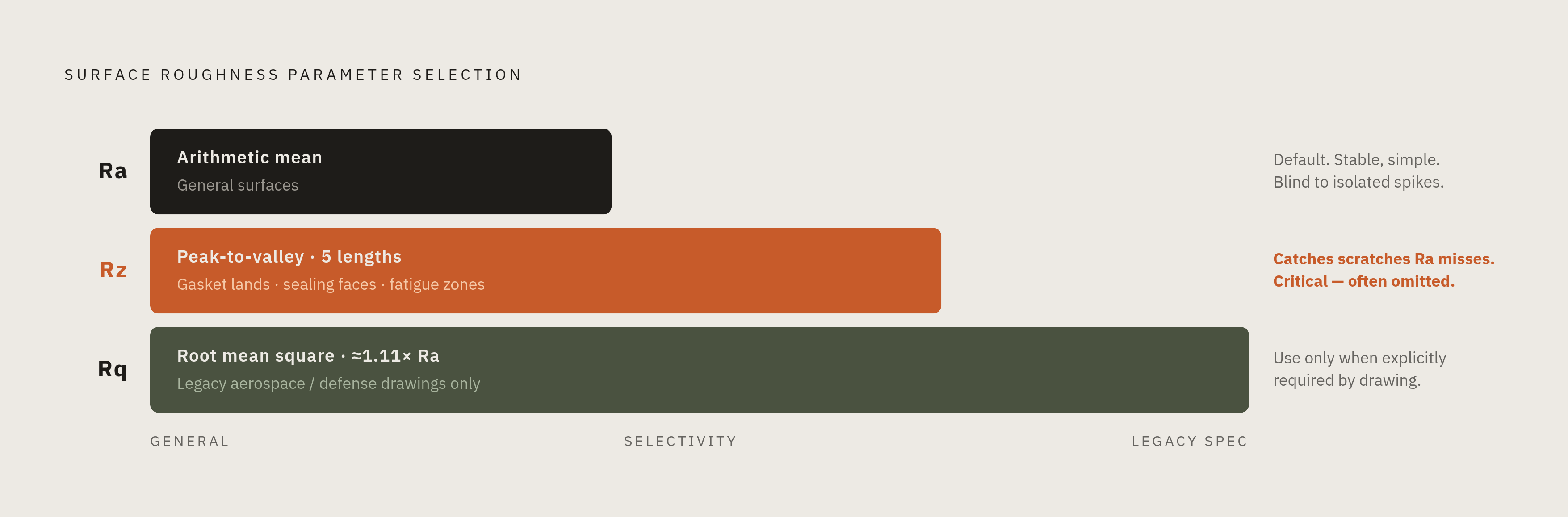
Ra, the arithmetic mean roughness, is the one most engineers reach for by default, and for good reason. ASME B46.1 and ISO 4287:1997 both define it as the arithmetic average of the absolute values of the profile's height deviations from a mean line, measured over a set evaluation length. It's simple to measure, it's stable from one reading to the next, and it's recognized across every major standard. Averaging is what makes Ra blind to shape. A surface with a few sharp, isolated spikes can post the same Ra as a surface with smooth, even undulations, even though the two will behave completely differently against a mating part or a seal. That gap matters most on sealing and fatigue-critical surfaces, where one deep gouge can start a crack or break a seal even if the average texture looks fine.
That's where Rz comes in. Rz measures the average of the peak-to-valley distance within each of five separate sampling lengths, so it catches isolated scratches and burrs that an Ra reading smooths right over. Two surfaces can carry the exact same Ra and very different Rz values: the one with occasional deep scratches will post a noticeably higher Rz, and that's the surface more likely to leak or crack first. Call out Rz on gasket lands, sealing faces, and any fatigue-critical feature where a single defect can cause a failure that a nice average would never flag.
Rq, the root mean square roughness, squares each deviation before averaging, so it weights larger peaks and valleys more heavily than Ra does. For a typical machined surface, Rq runs about 1.11 times Ra. Rq appears most often on older aerospace and defense drawings labeled "RMS. Rq is the modern version of that parameter, but a drawing calling for a given RMS value is not asking for the same thing as a drawing calling for a numerically identical Ra, and the two should never be treated as interchangeable. Where RMS is a genuine contractual requirement, measure it directly.
Beyond these three, ISO defines a longer list, Rp, Rv, Rc, Rt, Rmr, RSm among them, but most machined-part drawings never touch most of it. Dynamic sealing bores are the main exception, where Rmr (the material ratio) often gets called out alongside Ra or Rz. The working rule: Ra is the right default for general surfaces, Rz belongs on sealing, gasket, and fatigue-critical faces, and Rq only enters the picture when a legacy drawing or spec explicitly demands RMS.
What the standard roughness symbol encodes
Choosing a parameter is only half the job. That value has to land on the drawing in a symbol the machinist can read without guessing, and the symbol is governed by standards that assign a specific meaning to every position around it: ISO 1302 (now superseded by ISO 21920-1:2021) on one side, ASME Y14.36 (formerly Y14.36M) on the other. Putting the right value in the wrong spot makes the drawing specify something other than what the engineer intended.
The base shape itself has variants that each say something different. A plain check-mark symbol means a finish requirement applies without dictating how the surface gets there. A horizontal bar across the top means the surface has to be machined, produced by material removal. Add a circle at the vertex instead, and material removal is prohibited, so the surface has to stay in whatever condition it arrived in, whether that's cast, forged, or otherwise unmachined. A small circle added at the symbol's leg means the requirement applies all around the feature.
Around that base shape, each position carries its own piece of information. The roughness value itself, Ra or whatever parameter is in play, sits above the horizontal extension line, and that's the primary requirement a machinist reads first. Below that line goes any note on the machining process, treatment, or coating required to hit that finish. The sampling length, or cutoff, has its own defined position, and if it's left off, a default value applies automatically. Lay direction, which describes which way the dominant surface pattern runs, sits to the right of the check mark. On castings and forgings, machining allowance goes to the left.
Lay direction deserves its own attention, because it changes what a roughness reading even means. The common symbols are a parallel mark for a pattern running parallel to the projection plane, a perpendicular mark for one running across it, an X for a crossed pattern, an M for multidirectional (typical of face milling), a C for circular, and an R for radial. A profile measured along the lay looks nothing like the same surface measured across it, and the maximum roughness value is always the one measured across the lay. Leaving lay direction off a drawing means a perfectly good Ra value can still describe the wrong surface.
The unit trap that causes machined parts to come back wrong
One mistake accounts for more rejected parts than almost anything else in this discipline: mixing up micrometers and microinches. A bare number inside a finish symbol means microinches on a U.S. drawing built to ASME Y14.36M, and micrometers on a drawing built to ISO 1302, and those two scales differ by a factor of 25.4.
That gap bites hard in practice. Ra 32 µin describes a normal, economical CNC-machined surface, the kind that comes off a mill or lathe every day without any special effort. Ra 32 µm describes something coarser than a sand casting. A machinist reading a U.S. drawing under the wrong convention can turn a perfectly reasonable spec into something that reads as impossibly rough, or hand back a part finished far beyond what was ever needed, and either mistake traces back to the same missing unit.
The fix costs nothing and takes one habit: write the parameter, the value, and the unit on every single callout, as in "Ra 3.2 µm" or "Ra 125 µin," and set the drawing's general note to name the governing standard, ASME Y14.36M or ISO 1302, so the convention is locked in even for surfaces covered only by that general note.
What each machining process can deliver
A roughness value is also a claim about the process that will produce it, and a callout that the planned process can't reach without extra help is either a design mistake or a cost the quote hasn't accounted for yet.
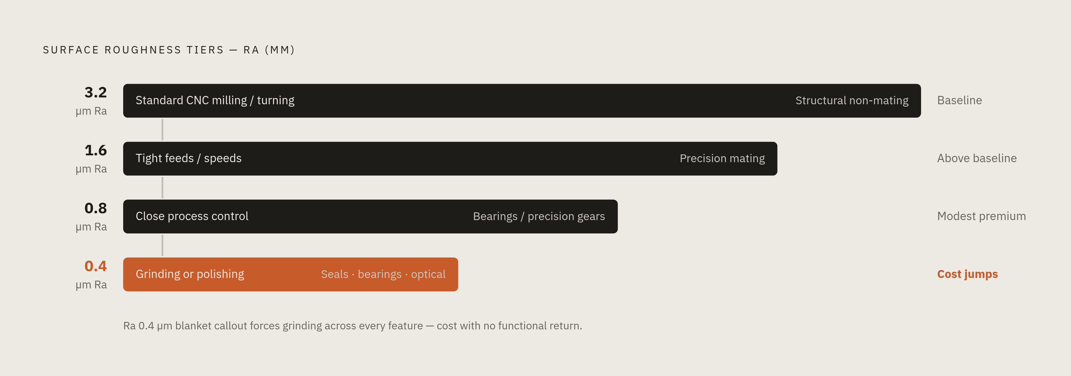
Standard CNC milling and turning, run with normal feeds and speeds, produce around Ra 3.2 µm. That's the standard economical finish straight off the machine, tool marks still visible, and it's the right call for structural, non-mating surfaces that never touch another part. Tighten the feeds and speeds and hold closer process control, and Ra 1.6 µm becomes achievable, the usual threshold for precision mating surfaces, with tool marks faintly visible but no longer functionally significant. Below Ra 0.8 µm, the game changes: hitting that finish takes very close process control and often a dedicated secondary operation, and cost starts climbing from there. Grinding is the operation most often called on to get a part there, with an achievable range of Ra 0.2 to 1.6 µm, and it's the standard answer whenever a drawing demands a finish finer than turning or milling can reliably hold on its own.
Specify Ra 0.4 µm on a surface that's going to be CNC-milled, and the machinist has no choice but to add a grinding or polishing step after the mill is done. If that tight value was applied as a blanket note across the whole drawing rather than targeted at the one or two surfaces that actually need it, that extra operation applies to every single feature, whether or not any of them needed it.
How tighter finish requirements drive cost
Every step tighter than the standard as-machined finish costs something, whether in machining time, added process control, or a full secondary operation, and that premium compounds fast as the Ra number drops.
Ra 3.2 µm costs baseline. Ra 1.6 µm runs noticeably above that baseline. Ra 0.8 µm adds a modest premium on top of that, and it's the right tier for bearings and precision gears where tool marks can no longer be visible. Ra 0.4 µm adds a meaningful cost jump again, often demanding grinding or polishing, and it belongs on critical seals, high-speed bearings, and optical surfaces, the places where the function genuinely can't tolerate anything coarser.
The costly mistake is picking a tight value and applying it everywhere. Set Ra 0.8 µm as a blanket note across a part with internal recesses, structural faces, and clearance holes that will never mate with anything, and the finishing cost multiplies across every one of those features while only a handful of them return any functional benefit.
The fix runs the opposite direction: set a general note that covers the whole part at the loosest finish the design can tolerate, Ra 3.2 µm for most milled and turned parts, and then call out tighter values only on the specific features that actually need them. That's the core discipline behind this whole exercise: specify a surface no tighter than its function demands, because every step finer than that is cost with no return.
Matching the roughness value to what the surface does
The right roughness value comes from what a surface has to do once the part is assembled rather than from habit or a safety margin added out of caution. Each functional category has a range that's both sufficient and economical, and a defensible drawing deliberately picks a value from within that range.
Static, non-mating structural surfaces, brackets, housings, clearance bores, need nothing beyond Ra 3.2 µm. The as-machined default is entirely appropriate there, and any tighter value is pure cost with no function behind it. Sliding or rotating contact surfaces, bearing bores, bushings, shaft journals, need Ra 0.4 to 0.8 µm, because low friction and a consistent lubricant film depend on a finer finish, and that value should be called out alongside the dimensional tolerance. Static O-ring and gasket faces call for Ra 0.8 to 1.6 µm: smooth enough for the seal to seat properly, but not so smooth that the elastomer has nothing to mechanically grip. Pipe flange faces follow a different logic. ASME B16.5 specifies a serrated concentric or spiral finish at Ra 3.2 to 12.5 µm, a texture that's deliberately coarse and patterned because it's built to lock the gasket in place.
Each of these ranges comes from what the surface actually does in service, not from a general instinct to specify the smoothest finish available. That's the standard every roughness callout on a machined part drawing should be held to.
Sources
- Surface Roughness Average (Ra): Chart, Formula, and Conversion Calculator
- Surface Roughness Chart: Ra, Rz, RMS & N-Grade Conversion
- Surface Roughness Symbols On Drawings - Additive Innovation Hub
- Understanding Surface Roughness Symbols
- Paper ID #23551 Understanding Surface Quality: Beyond Average Roughness (Ra)
- Surface Roughness Guide: Ra Rz, ISO 21920 & Mitutoyo Surftest