Wire EDM Design Considerations for Complex 2D Profiles
How to design internal corners, start holes, and slot geometry so wire EDM cuts them right.
Wire EDM cuts metal with electricity, not force. A thin wire, charged and threaded through the workpiece, throws sparks hot enough to vaporize metal without ever touching it, and that single fact explains almost every design rule that follows. Get the physics wrong on paper and the shop either negotiates a change order or breaks a wire mid-cut. Get it right, and complex 2D profiles come off the machine holding tolerances that milling can't touch.
Start with what's actually happening at the cut. Each discharge fires across a gap of 10 to 50 microns, maintained in a bath of deionized water that acts as the dielectric. The spark hits over 10,000°C for a few millionths of a second and vaporizes somewhere between 0.001 and 0.01 cubic millimeters of material. Do that thousands of times a second, move the wire along a CNC-programmed path, and the part's outline shows up as a through-cut, a profile whose exact shape is whatever path the machine was told to trace.
Two things fall out of that mechanism immediately. First, there's no mechanical force on the part, so no deflection, no burr, no chatter. Second, the wire's own diameter (typically 0.1 to 0.3 mm, though fine wire goes down to 20 microns) sets the kerf, and that kerf is a real, physical gap the wire has to pass through. It isn't a cosmetic detail. It's the reason corner radii, start holes, slot depth, and tolerance all have hard floors.
One more foundational point: wire EDM only cuts all the way through. It can't stop partway down and leave a blind pocket, that's sinker EDM's job, a different process entirely. Every profile designed for wire EDM has to go full thickness. Keep that in mind before laying out any feature that looks like a pocket.
The internal corner radius constraint and what designers get wrong about it
The wire has a diameter. To cut an internal corner, it has to travel around that corner, and a physical object with width can't pivot on a point. That leaves a radius behind, roughly half the wire diameter plus the spark gap, whether the designer wants one or not.
In practice, that floor lands somewhere between 0.05 and 0.2 mm depending on wire size, with the finest wires reaching down to around 0.025 mm. A radius of 0.002 inches is genuinely achievable with the right wire, which is tighter than any end mill will ever manage. But zero is not on the menu. Sharp internal corners, true R0, don't exist in this process.
Here's where designers trip up constantly: they dimension an internal corner as sharp because the intent was just "make room for the mating part," not because a truly zero radius mattered. Nobody asked for R0 on purpose, it just fell out of the CAD default. That forces the shop to either call and negotiate a radius after the fact, or push a wire past its limit and snap it mid-cut. Neither outcome helps the schedule.
The fix is simple: figure out the smallest radius the function can actually tolerate, put that number on the drawing, and check it against the wire diameter the shop plans to run. That's a five-minute conversation early that saves a redesign later.
And this constraint cuts both ways. Acute internal angles and very fine internal features are exactly where wire EDM has no real competition. CNC milling is bound by end-mill diameter, so a tool simply can't reach into very tight internal corners the way wire EDM can. Wire EDM gets to roughly 0.13 mm, wire-size permitting. If a design calls for internal angles sharper than that 0.4 mm threshold, wire EDM isn't just an option, it may be the only subtractive process that can make the part at all.
Start holes: the access constraint that must be designed in, not worked around later
Wire EDM can't start cutting in the middle of solid material. To cut anything internal, a slot, a window, a perforation, the wire has to thread through a hole that already exists. External profiles cut from the edge of stock don't need this. Anything enclosed does.
That start hole isn't a shop-floor afterthought, it's a design decision, because its location determines where the entry witness mark lands on the finished part. Put it somewhere that gets machined away in a later op, or somewhere buried in the scrap slug, and nobody ever sees it. Put it on a functional surface by accident, and now there's a visible mark exactly where a mating part needs a clean face.
When there's no natural access point for the wire, a small-hole EDM process (often called hole popping) drills the entry. That process can put a hole as small as 0.004 inches in diameter, at depth-to-diameter ratios up to 100:1, and it does this in carbide and hardened steel at speeds above one inch per minute. It's a legitimate solution, not a workaround, but it's an added operation with its own cost and lead time.
A related detail that gets missed: keep part thickness consistent through the zone where the start hole goes in, as variations in that area can affect the quality of the entry hole and the cut that follows it.
Complex profiles with multiple internal cutouts need one start hole per cutout, no exceptions. Map that out on the drawing before it reaches the shop. Leaving start holes off the print entirely is one of the most common quoting headaches in this business: the shop has to add an unplanned hole-popping step, and that cost and delay could have been designed out from the start.
Slot geometry, wall thickness, and the wire deflection limit that sets the depth-to-width boundary
Wire EDM cuts slots as narrow as 0.004 inches, holding tolerances down to ±0.0001 inches. Milling can't approach either number. But there's a geometric ceiling on how deep a slot that narrow can go.
Push a slot past roughly 50 times its width, and the wire starts to bow under flushing pressure and spark forces. The straightness of the slot wall degrades, tolerance drifts, and the cut quality falls apart the deeper it goes. A more conservative rule that shows up across the industry: keep feature depth to somewhere between 10 and 15 times the wire or electrode diameter, well short of the hard 50:1 failure point.
Below that depth ratio, the next risk is wall thickness. Cutting force is zero, sure, but that doesn't mean thin ribs and walls sit still. Raw stock carries residual stress from rolling or prior heat treatment, and once a thin section gets severed from the surrounding material, that stress releases. A narrow rib in aluminum, for instance, can shift position mid-cut purely from stress relaxation, no cutting force required.
A few ways to manage that risk: rough-machine the blank oversize before final cutting, stress-relieve the material ahead of time, or sequence the cut paths so thin features get cut last, after the surrounding stock has done its job of holding everything in place. That last option costs nothing but forethought, and it means telling the programmer directly rather than letting the software pick a default path order.
Flushing matters here too. A deep, narrow slot restricts dielectric flow, and poor flushing raises local temperature, degrades surface finish, and raises the odds of wire breakage. Depth and width limits aren't just geometric, they're thermal.
Taper, U/V axis control, and the difference between a 2D profile and a 3D prismatic feature
Standard wire EDM runs with the wire perfectly vertical, extruding the programmed profile straight through the part thickness. That's a pure 2D shape pushed through in the Z direction, nothing more.
Machines with four or five axes add independent motion to the upper and lower wire guides, the U and V axes, letting the wire tilt. Tilt the wire, and the top of the cut can be a different shape or size than the bottom. That opens up draft angles on punches and die inserts, extrusion dies where the profile changes across the material's thickness, and prismatic shapes no single milling setup could produce.
Anyone designing forming tooling, stamping dies, or precision inserts should treat taper as a live option, not a specialty feature reserved for exotic jobs. If a die needs a clearance angle, put the angle directly on the wire EDM drawing rather than routing it to a separate grinding step. A shop running a capable four-axis machine produces both in one setup.
One limit worth keeping in mind: this is controlled, ruled-surface tapering, the wire sweeps between a fixed top position and a fixed bottom position. It's not freeform 3D contouring. And extreme taper angles, or very thick stock, can exceed what the upper guide's travel allows on a given machine. Worth a quick call to the shop before the taper angle gets locked into the design.
Kerf compensation, dimensional accuracy, and how multi-pass strategy determines what tolerance the part actually holds
The wire's kerf, its diameter plus the spark gap, means the programmed toolpath sits offset from the finished edge. Machines compensate for this automatically. But designers still need to understand what that offset means for bilateral versus unilateral tolerances on any feature that mates with something else.
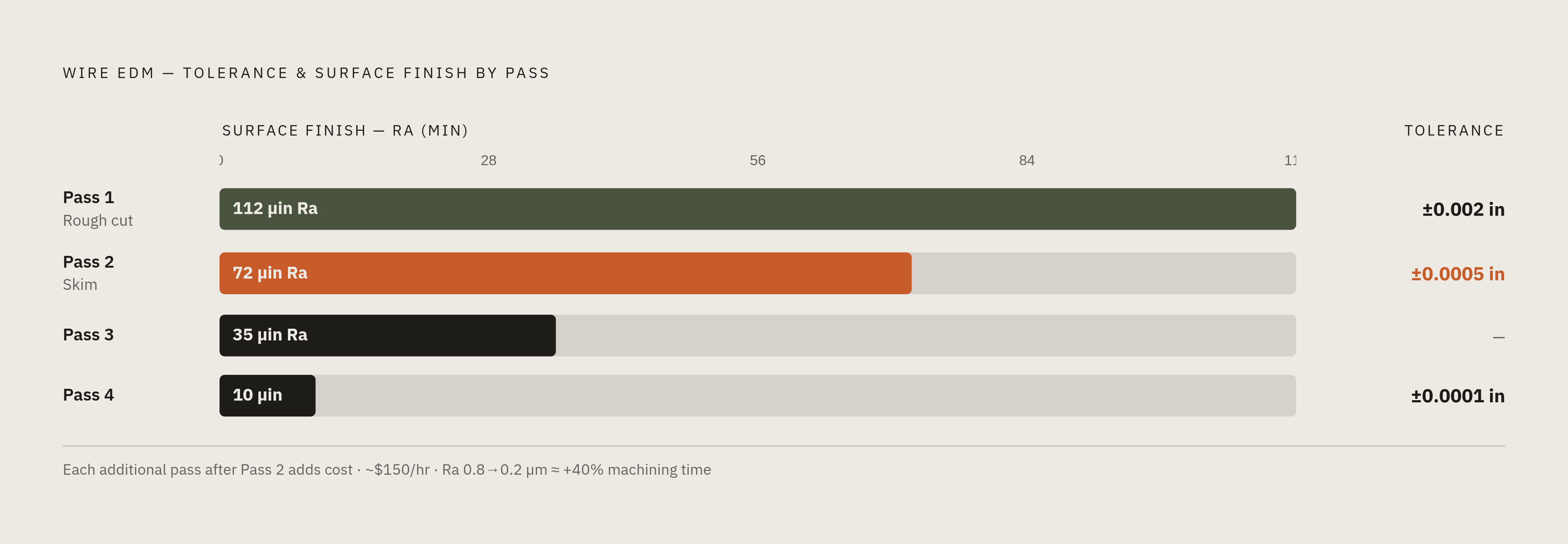
A single rough cut gets a part to roughly ±0.002 inches, with a surface finish around 112 microinches Ra. That's fine for slugs, fixture plates, and profiles with no critical mating surface, and it covers something like 90% of wire EDM work. A second pass, a skim cut, tightens that to ±0.0005 inches and about 72 microinches Ra. Third and fourth passes bring surface finish down to 35 and then 10 microinches. Push further, under tightly controlled conditions, and the process reaches ±0.0001 inches (2 microns), with dedicated micromachining shops going below 1 micron.
None of that comes free. Moving surface finish from Ra 0.8 microns down to Ra 0.2 microns adds roughly 40% more machining time, and at a typical shop rate around $150 an hour, that's real money added directly by a finish callout. The rule here is straightforward: specify the tolerance and finish the part actually needs functionally, nothing tighter. Over-specifying finish on a face nobody will ever measure is one of the most avoidable cost drivers in this whole process.
There's a metallurgical wrinkle too. Every pass leaves behind a recast layer, material that melted and resolidified rather than being cleanly removed. For parts under fatigue or dynamic load, that recast layer matters, and the fix is a final low-energy skim pass specified on the drawing. Left silent, the shop defaults to the economical two-pass cut, recast layer included. Modern CNC wire EDM machines can position to roughly ±0.00004 inches and hit finishes as fine as 4 Ra microinches through an optimized multi-pass sequence, but that capability only shows up on the finished part when it's specified, sequenced, and paid for.
Material conductivity and thermal properties: what actually controls cut speed and surface quality
The material has to conduct electricity. Plastics, ceramics, and non-conductive composites are off the table for conventional EDM, full stop, though specialized assistive-electrode variants exist that can machine certain non-conductive ceramics and composites.
Hardness plays no role in cutting speed. A D2 tool steel insert at 62 HRC cuts just as reliably as the same steel annealed and soft. That single fact is why wire EDM is the standard choice for finishing tool steel after heat treatment, when milling would chew through carbide end mills in minutes.
What actually sets the pace: electrical conductivity, melting point, and thermal diffusivity. Different materials behave in predictable, distinct ways.
Tool steels, D2, A2, H13, S7, M2, cut predictably even fully hardened. D2 at 58 to 62 HRC is probably the single most common material run through wire EDM shops, and it holds tolerance well with a manageable recast layer. Tungsten carbide cuts at 40 to 60% of tool steel's speed and costs 40 to 80% more per inch of equivalent geometry, but conventional machining destroys tooling against carbide, so wire EDM often ends up the only practical route. Stainless steels like 304 and 316 run about 20% slower than carbon steel due to lower thermal conductivity, and they're prone to micro-cracking in the recast layer if the power settings run too aggressive, so dialed-back settings and lighter skim passes matter here.
Aluminum, 6061-T6 and 7075-T6, cuts two to three times faster than steel thanks to high conductivity and a low melting point, though the first pass comes out rougher and pitted, needing more skim passes to clean up. Given that speed advantage doesn't always translate to cost savings, wire EDM is rarely the economical choice for aluminum when CNC milling is sitting right there as an option. Titanium (Ti-6Al-4V) is less conductive than most EDM metals, cuts slower, and its high melting point brings recast and cracking risk, which means careful pulse control and flushing management, landing around ±0.005 to ±0.01 mm on achievable tolerance.
Superalloys such as Inconel 718 work-harden severely under cutting force, which makes conventional milling brutal and expensive, and other demanding superalloys present similar challenges. Wire EDM sidesteps that problem entirely since there's no mechanical force to trigger work-hardening in the first place. The cutting rate is slow, but it's still cheaper than trying to mill these alloys at full hardness.
Wire choice tracks material choice: brass covers general-purpose work, molybdenum and tungsten handle fine-feature micromachining, and coated wires step in for demanding alloys where both speed and surface finish need to hold up. The bottom line for design: if a part gets hardened before machining starts, wire EDM is almost always the right call. Running a mill against D2 at 62 HRC burns through carbide end mills in minutes.
When wire EDM is the right process choice and when it is not
Wire EDM is not fast. Nobody should pick it expecting throughput, it wins on geometry, hardness tolerance, and precision, not speed.
Against CNC milling: wire EDM wins on hardened material above 50 HRC that can't be soft-machined first, on internal corner radii tighter than any end mill can reach, on tolerances below ±0.0005 inches, and on thin or delicate features where any cutting force would cause deflection. Milling wins on bulk material removal, true 3D surfaces, softer materials where tool wear stays manageable, and faster cycle times whenever the tolerance allows it.
Against laser cutting: wire EDM wins on thick stock, tight tolerances, hard materials, and profiles where a heat-affected zone on the edge isn't acceptable. Laser wins on thin-to-medium sheet stock, very high speed on thin material, and a broader range of materials that includes non-conductors laser can cut and EDM simply cannot touch.
Volume changes the math in a specific way worth remembering: wire EDM cycle time per part doesn't drop as quantity goes up. Every single part takes the same machining hours regardless of order size. Higher volume only spreads out the setup, programming, and first-article inspection costs over more units, it does nothing to the per-part cut time itself.
That means for a run of, say, 5,000 units in a material that can be machined soft and hardened afterward, conventional CNC plus heat treatment almost always beats wire EDM on cost. The calculus only flips toward EDM once hardness or geometry rules out the soft-machine-then-harden path entirely.
As a quick gut check at the design stage: if a profile combines hardened material, internal corners tighter than 0.4 mm, or tolerances beyond what milling can hold, wire EDM stops being one option among several. It becomes the process the geometry actually demands.